


dewster said: When it comes to feedback sign, I find my first mental take is almost always wrong, so I was banging my head trying to get it to see a light that wasn't there!

dewster said: When it comes to feedback sign, I find my first mental take is almost always wrong, so I was banging my head trying to get it to see a light that wasn't there!
Interesting LC Buffer Behavior
Discovered this morning that I'm not giving the phase detector enough dynamic range (counter bits), which causes it to modulo roll over / under, which causes lock problems with lower frequencies - frequencies much lower than tank resonance. Fixing this is simple and should make the phase lock much more robust and self-starting. While looking into this I've been thinking of adding some sort of assist to the phase detector to generally improve the bandwidth it can cope with. You have to do this kind of stuff very carefully, as it can easily introduce non-linearities and unintended behavior. Since the LC is a low pass filter, the I/O phase delay will be near zero degrees below resonance, near 180 degrees above resonance, and 90 degrees at lock. With this limited range one might think an XOR is ideally suited to the situation, and it pretty much is. But the tank drive is a square wave, so the strong odd harmonics of a lower frequency driving the tank could confuse things, causing a lock to a harmonic rather than to the fundamental.
I've been aware that the buffer I'm using, an NPN / PNP pair arranged in a non-inverting follower configuration, has a rather large dead-band. The drop across the emitters lowers the output voltage swing, though this probably isn't an issue. The buffer can pull in both directions, but it doesn't provide a low impedance if the thing it is driving decides to pull the other way. I haven't considered this to be an issue, since at resonance the tank doesn't do this, but when not at resonance it can and will, and I noticed some unexpected and rather nice behavior regarding this that I'd like to share because it means we can use a simple XOR phase detector over a very wide range of frequencies.
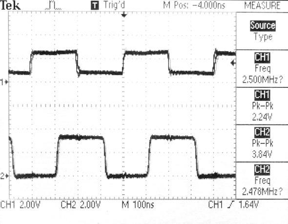
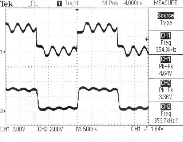
The above is a scope shot of the NPN/PNP buffer output driving the tank at the top, and the tank output (capacitive divider and twice inverted) on the bottom which feeds the FPGA board. You can see the top signal amplitude is roughly two diode drops below the 3.3V supply, and that the tops and bottoms are somewhat concave, indicating current draw from the tank. Note that the bottom signal lags by roughly 90 degrees, the lock condition for the phase detector, though to obtain the data shown here I am simply manually manipulating the drive frequency via the command line and the resonance frequency with my hand.
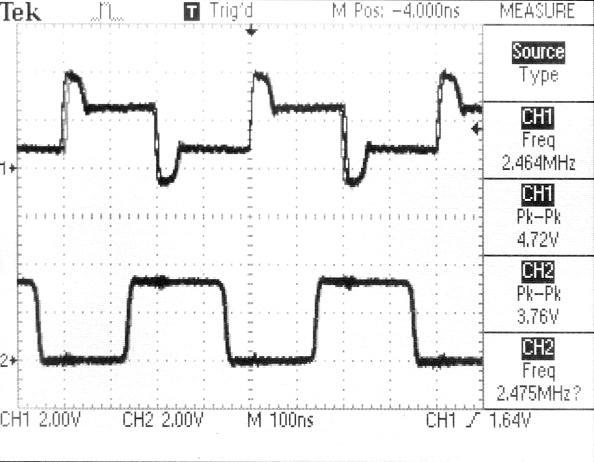
Above I've brought my hand near the antenna, dropping resonance / causing the drive frequency to be too high, which makes the phase difference larger than 90 degrees. Note the buffer has spikes that go one diode drop beyond the supply as the collectors reverse bias and clamp to the supply rails. The spikes are due to the buffer trying to drive the tank too early in the other direction, when it is still trying to pull current from the buffer. Note that this isn't a huge deal in terms of the integrity of the lower signal being sent to the FPGA.
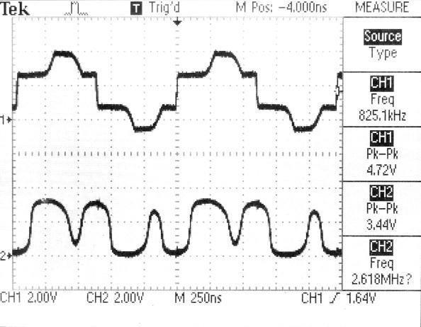
The above is what happens when the drive frequency is 1/3 of the resonance frequency. "Bumps" at the resonance frequency can be seen riding on top of the drive, and they are fairly high amplitude due to the inability of the buffer to constrain the opposite swing. This is reflected as dips in the signal going to the FPGA at bottom (so we wouldn't want to use an edge detecting phase detector here) but the overall duty cycle and phase are clearly correct (slightly larger than zero because the drive frequency is way below resonance) so the XOR result will be directionally correct and drive things to lock. If the buffer presented a continuous low impedance to the tank we would see a sine wave on the bottom, and the XOR wouldn't know what to do with that, so the discontinuous output impedance is actually a plus.
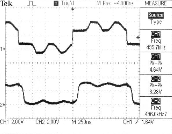
The above is the 5th harmonic driving the tank, it isn't nearly as bad looking as the 3rd harmonic, and the signal going back to the FPGA will give the XOR a very clear indication of which way to drive the output frequency.
And here is a view of the 7th harmonic driving the tank to resonance, it shouldn't be a problem either. And this brings us near the bottom in terms of output frequency range of the numerically controlled periodic delay, so no other harmonics should be an issue, and the XOR should be able to lock over the entire range.
The only place phase gets ambiguous is when driving the tank above 4MHz or so, so if we start things out low it should seek out and lock to the fundamental without issue, and almost no matter what value inductor we use. I haven't actually tried this out yet but I trust it will work. If lock robustness is confirmed, I may make the pitch side oscillator purely digital hardware and only use software to process the operating point data. The volume side will likely use a HW / SW combo loop, as previously discussed (ad nauseum - sorry about that, Chief).
[EDIT] TL;DR: A quirk of the tank drive buffer is that it doesn't provide a low impedance if the inductance pulls the other way. Fortuitously, this behavior allows a simple XOR phase detector to be used over a very wide range of frequencies.
Sorry about that Chief - Today is your Birthday

William "Will" Sampson, Jr. (September 27, 1933 – June 3, 1987) was a Native American actor
Dewster, recently i purchased a Casio MT-400V. I guess you already stumbled across its voice generation. I don't get how it works, but in case of you don't know what it is all about: https://en.m.wikipedia.org/wiki/Vowel–consonant_synthesis. Might be interesting for digital timbres as i think that some voices sound quite good.
Hi Dominik,
No I hadn't encountered that one. Found this page on a variant:
http://weltenschule.de/TableHooters/Casio_CT-410V.html#ConsonantVowel
Haven't gone patent hunting, but it seems square wave based, so I suppose I'm not super interested, but I do appreciate the pointer and had fun reading about it.
The name "vowel-consonant" seems to imply human voice synthesis, but that's not the case. I believe it's just morphing between two multi-pulse square waves.
You are welcome. I thought square wave and digital might fit the bill, but you guess it: i don't go that routes and just were guessing..
Anyhow. At least the voices oboe and cello (ok, with the analoge filter ON) would be something i'd like to have being choosable with the theremin.
Dominik, I can actually do analog equivalent stuff (DSP) in the processor, so I'm not limited to square waves and such with the audio generation and processing.
=============
NCO
Have been spending a lot of time coding and demoing various approaches to the pitch antenna side of things. It's quite clear to me that the highest quality sensing is best done entirely in hardware, and with an NCO rather than my NCPD as the signal source (LC tank drive). The NCPD is really nice in that the parameters and loop gain and such are quite obvious, but I can't seem to get rid of tiny islands of instability in the pitch field. Tried messing with the dither amplitude, and tried four LSbs set to one, but I finally gave up on that avenue. Yesterday I worked on a spreadsheet that calculates and helps me understand the various parameters when an NCO is used in a delay-based phase locked loop, and today I have what I believe is the ideal NCO construct for this:
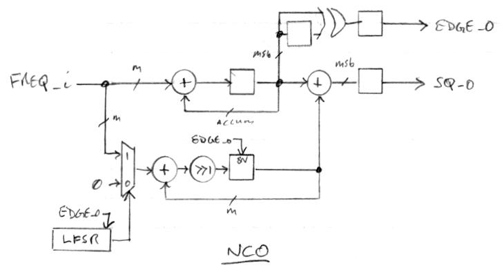
The top most loop is the phase accumulator, and the bottom loop is the dither noise generator. The noise is scaled to the range from zero to FREQ_i by successive right shift and accumulation of FREQ_i or zero, gated by a pseudo random bit from an LFSR generator. The noise is updated by one add and shift on each edge, rather than all m bits on each edge, which seems sufficient. I also have the two LSbs of FREQ_i set to one to keep the LSbs "busy".
Running right now on the bench with a license plate antenna. The loop is a simple XOR phase detector followed by a 24-bit up/down counter to integrate. With 16.667 ms scope delay it's rock solid and very smooth. This scope delay forms a comb filter for 60 Hz noise, using non-integer periods of delay clearly show the influence of mains hum on the signal. So hopefully the hum will be easy to filter out downstream in software.
I believe the reason an NCO works better here is that the NCO is accumulating a constantly changing input, which makes the operation more chaotic than that of the NCPD, which only grabs an input value every half output cycle.
The lock range is super wide (essentially 0Hz to ~4MHz) and completely automatic (as long as operation is restricted to be below ~4MHz), for reasons given a couple of posts up. I believe the loop bandwidth I'm looking at is ~1kHz, but it's kind of tricky to figure it out with an NCO in the loop, and the bandwidth likely changes a fair amount as my hand approaches the antenna.
[EDIT] I swapped coils from 324uH to 268uH in the live circuit and it popped right back into phase lock, so this arrangement looks like it's set and forget in terms of hardware (no need for software to give it a "kick"). Now to mount it in the prototype, and move on to finalizing the volume side hardware.
Pitch Side
Mounted the tank board in the pitch antenna plate plastic box yesterday and started dissecting cable candidates in the junk box in order to do the interconnect. I discovered that an old style VGA cable actually has three coaxial cables as well as a bunch of other misc. wires inside, and would most likely work quite well. A DVI cable has four individually shielded twisted pairs, which would probably also work well. This morning I cut apart a CAT-5 cable, which has four unshielded twisted pairs inside, and gave that a go. I simply grounded the other twisted wire at the source, but not at the destination, in order to give some shielding but to not cause ground currents or loops. One pair provides the tank drive, two other pairs the zero and quadrature return, and I'm using the fourth pair to provide 5V power to the board (which is regulated to 3.3V).
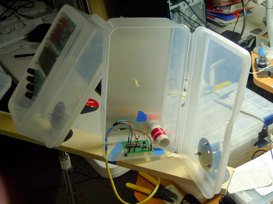
The above shows the pitch antenna plate box hinged open so you can see how things are arranged. If I'd thought about it more I may have laid out the PWB opposite, so the coil would be positioned as far away from the control box (on the left) as possible, and the cable closest, but it's probably not that big a deal for the prototype. Might actually be best from an electrostatic shielding point of view to have the coil mounted at the center of the plate. The FPGA board is currently sitting on my desk (and not installed in the control box quite yet).
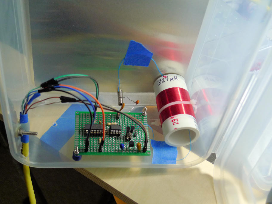
Here is a close-up of the board / coil / cable. The two small pieces of blue tape secure the coil wires to reduce problems with vibration. The cable is affixed via a cable tie. Interconnection (on both ends) is via small jumpers. I used a small coil spring to make the coil and sense capacitor (1pF) electrical connection to the plate antenna. The 324uH tank coil is secured to the box with a plastic wire tie.
It's running right now, resonance is around 2.35 MHz. With the scope probe a few inches away from the plate there is ~6 Vp-p on the scope, which drops to ~1/2 that when my hand is about 1" from the plate antenna. Sensitivity is quite high, and the interconnecting cable doesn't seem to be messing with loop lock or anything. Probably sounds stupid, but I've been kind of dreading this point in the project - when detecting at the attofarad level, literally anything can go wrong - so huge sigh of relief!
You must be logged in to post a reply. Please log in or register for a new account.

