Let's Design and Build a (mostly) Digital Theremin!

Posted: 11/10/2017 6:46:01 PM
dewster

From: Northern NJ, USA

Joined: 2/17/2012

What's Happening?

So I've got assembly code running that grabs the pitch info and linearizes it via the method described above.  The LCD allows me to observe (via more code) 32 bit hex values at any point in the chain, and the 4 encoders (via even more code) allow me to easily alter up to 4 values.

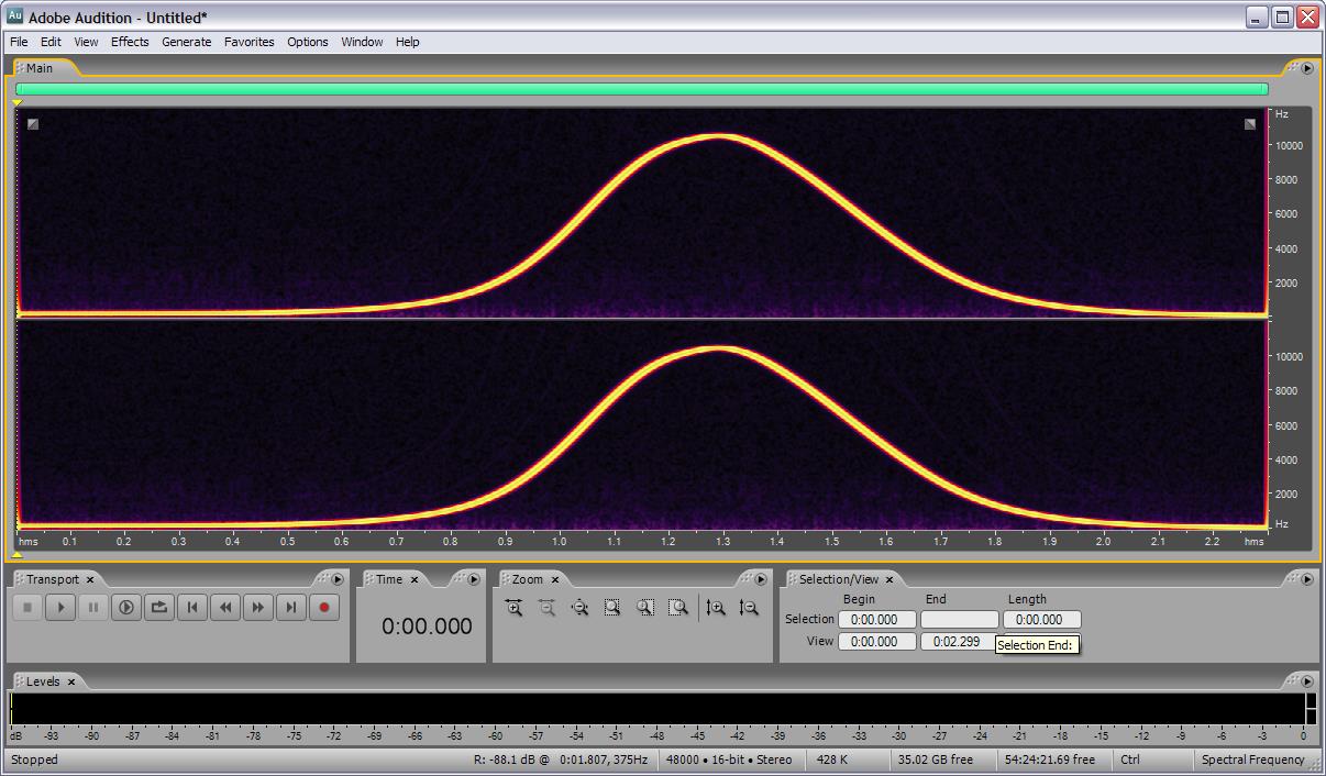
I've also got code that takes the linearized pitch number and performs PWM on the LED tuner.

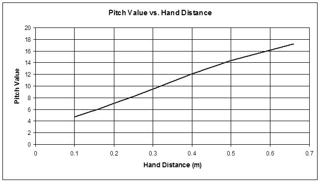
I'm seeing pretty much what my spreadsheet predicts in terms of linearity, the pitch change poops out in both nearfield and farfield, with maximum change in the mid field.  The gain difference is quite noticeable, on the order of 50% or so, and isn't nearly sufficient in terms of linearity.  So that's a disappointment.

The LED display is maybe too antsy seeming to really be useful.  I've tried both positive (only one LED on) and negative (only one LED off) modes.  One thing that helped a lot was squaring the subnote data before applying the PWM count, this seems to compensate pretty well for the log response of the eye to brightness.  I also need to try not modulating the center LED to see if that helps readability.  Another thing to try is applying a slight brightness to all the LEDs with an otherwise positive type display.  I'm hoping some combination of things will make it useful, otherwise the hardware needs a redesign.  I'm running the LEDs at bare minimum brightness (settable via a register in the serial driver) as anything higher is blinding to stare into, so I should probably lower the analog current set resistor on each serial driver to something lower than 15mA max.  The PWM cycle rate is 180Hz (to get filtered out by a CIC hum filter notch) and there are approx. 256 gray scales.  The display doesn't seem to be noticeably influencing the pitch field (huge relief).  The octave is a hex number on the seven segment display that transitions via PWM at the B to C note transition.

As for linearity, my edit in the previous post is due to my not mentioning the fact that AFAIK the operating point for the open.theremin is not exponentiated before being fed to linear NCO code.  In my spreadsheet I applied a log2 function to the linearized data and believe it or not it looks to have almost exactly the same shape both before and after the log2!  So the numbers coming out of linearization are somewhere between linear and exponential (I think ILYA was trying to tell me this).  Weird.  I would prefer linear so that the display can be fed directly and the NCO input exponentiated, otherwise I would need to do log2, offset and gain, and then exponentiate.  I can't believe how much time I've put into linearization theory only to end up here with very little to show for it.  I'm thinking of trying curve fitting in Excel to generate a simple polynomial to make the raw data (or some simple transformation of it) linear.  But I don't want a bunch of things to adjust, anything beyond one or two knobs gets overwhelming, and I can see why they automated the calibration process in the Theremini.

Anyway, except for actually making noise, IT'S ALIVE!

Posted: 11/12/2017 11:08:53 PM
dewster

From: Northern NJ, USA

Joined: 2/17/2012

Been back in the linearity mines for the last few days (ugh) and I found what appears to be a good simple solution in Excel simulation, but I haven't tried it on the prototype yet. 

It seems the inverse of the square root of the frequency difference gives really good linearity in the near and mid fields:

  d ~= 1 / (K0 - f)^0.5

or 

  d ~= (K0 - f)^(-0.5)

And obviously with a small vertical offset:

I didn't include the sensitivity graph, but it looks like it's good to maybe 10% or so over the 0.1 to 0.5 meter range.  The far field response past 0.5 meters is geometrically dominated by the hand merging with the body, and so is almost impossible to really linearize via simple means.

This is from my "virtual Clara" C sims with a plate antenna, I imagine the power (-0.5 = inverse square root) would vary for other antenna geometries.  I have both integer and floating point square root subroutines, as well as floating point inverse, but one should be able do it all (square root and inverse) by taking log2, multiplying by -0.5, then taking exp2.

What's nice about this is the linearizing factor (the power) is likely a constant for a given antenna geometry, if so then it's a "set-and-forget" type parameter that would only require rare touch-up, and could be buried in a menu somewhere.  The user would only have to set one parameter (K0) to compensate for environmental C.  It's been my experience that these types of adjustments have to be kept as dead simple as possible.

Posted: 11/14/2017 4:05:47 PM
dewster

From: Northern NJ, USA

Joined: 2/17/2012

Got the above working on the prototype a little bit ago.  A power of -0.25 seems to make it pretty linear, though there is some obvious pooping out near the antenna (~<0.1m).  Tuning it is fairly easy, just step back a bit and adjust for far null.  With more filtering I could probably play a rough tune a couple of meters out by waving my forearm.  So it seems linearity is sufficiently solved (for now at least).

Still mucking around with the pitch display, not sure what where that's going.  I've tried turning the center LED off and that seems to help interpretation.  Maybe it needs more LEDs, or something to make the notes more geometrically individual looking.  Not sure color difference is all that good for that, thinking of replacing the blue LEDs and the center green LED with white (i.e. making the note display entirely white LEDs).  Right now I've got a positive display going with the subnote info squared twice.  I need to change the current sense resistors anyway.

Posted: 11/15/2017 8:54:50 PM
dewster

From: Northern NJ, USA

Joined: 2/17/2012

Replaced all the colored note LEDs with white LEDs, This seems to help a lot with seeing what note is being played, but I kind of miss the nice symmetric color pattern. I've got the center LED non-modulated (on all the time) which also seems to help readability.

Lowered the minimum LED drive to ~0.5 mA by increasing the current sense resistors to 3.3k Ohms.  The LED serial drive ICs only give a current drive range of 1 to 1/12, which really isn't enough to adjust over a full range of brightness. You want full blast 20 mA or so for sunlit scenarios, but 1/12 of this is too bright for dimly lit scenarios.  One could always do PWM to lower the bottom end I suppose, but I'd prefer to do this digitally so as not to splatter the system with noise.

I'm not seeing any visual indication that the note/octave display is interfering with the pitch field.  The PWM cycle rate is set to be super close to 180Hz, so it sits squarely in a zero of the CIC hum filter.

========

In Hive I yanked out the byte and half word copy opcodes (due to disuse) and installed an endian byte swap opcode (otherwise awkward to do in assembly).  I wish there were immediate 8 and 16 bit mask instructions as this pops up now and then in my assembly - may add them at some point.

Posted: 11/17/2017 2:37:52 PM
dewster

From: Northern NJ, USA

Joined: 2/17/2012

Doing a lot of thought and some experimenting regarding the best way to implement the pitch side sense reversal, as well as the user gain and offset controls.  Rather like the audio chain on a mixer board, there are multiple points at which the numbers can clip, go modulo, etc.  But the user only experiences the final result of the mathematical manipulations, so any evidence of trouble somewhere in the gauntlet could easily be hidden or confounded.  And the process is already probably complex enough seeming for the average person, with linearity control K1 (linearization power) and far field null control K0 each influencing overall gain (though I'm becoming fairly accustomed to it).

It helps to have previously developed float and int assembly math packages, as I'm aware of numeric and bit twiddling tricks that can come in handy here.  One in particular is the logical NOT of an unsigned int, which reverses the direction of change.  I'm using this to make the pitch number increase rather than decrease as the hand approaches.  It's gain sensitive, but not overly, so an offset of the last float exponent seems to work well in terms of converting the float magnitude to int.  I'm relying on the limiting action of my float-to-unsigned-int subroutine to confine the output range, and that's working well too.  Seeing ~30 or octaves of change here which is plenty.  (As with analog synthesizers, you need a gain standard to define what an octave is, like 1V/octave.  The way I'm defining octaves is by taking a cue from the 5.27 input of the unsigned int EXP2 function, where the top 5 MSbs are the octave info, and the lower 27 LSbs form the octave fraction.  I'm using the same convention at the input of the LED tuner.)

After this I plan to apply a simple unsigned extended multiplication, the result of which cannot overflow because it is an attenuation, followed by a signed offset, the result of which can both overflow and underflow, and so will need explicit limiting.  The signed offset adjustment will probably be one note per detent of the encoder.  The gain adjustment should "hinge" at the far-field offset null point, which I hope will be the most intuitive for the user.

Some kind of "dumb" mode to aid rough setup is perhaps called for, which could entail just the zeroing out of the final offset, the display of the intermediate operating point there, etc.  Automation could be employed, though I think Theremin users are probably used to doing manual setup and would prefer it?  Manual setup keeps one in shape when it comes to really understanding the instrument.  Automatic setup is what makes the operation of the Theremini so opaque IMO, the procedure is diddling hidden internal parameters, altering them all en masse when you maybe only want to change one or two.  The only automation I'm considering is something I implemented on my first prototype, where at power-up or reset the null point is calculated. The user then just touches it up.

[EDIT] There have been several "make-or-break" points in this project and, as a developer, facing them has been "exciting".  The first was early on, where I was doing calculations and simulations for months in order to determine if the digital / FPGA approach was feasible, and then coaxing the initial prototype hardware to behave the same as the sim.  Another scary point was wiring up the antenna units and seeing if they would function with a couple of feet of wire between them and the FPGA board.  Until it was done, I thought the whole CIC method of operating point downsampling might dead-end.  CIC as a hum comb filter replaced an inferior high Q variant I'd found in a paper - and the CIC seems rock solid.  Firing up the tuner for the first time several days ago was somewhat hair-raising, as I half expected it to interact with the pitch field.  Linearity has been a constant thorn that also came to a head several days ago.  These user interface adjustments are equally important to get right IMO, because what good is a Theremin that's too complicated to actually set up and use?  There are so many ways to ruin an otherwise sound approach, perhaps the easiest is not spending the time necessary to refine each element of the design and properly integrate it into the whole.  The longer one spends on development, the higher the expectations from everyone, including me.  But it's often a diminishing returns kind of thing.

Posted: 11/19/2017 5:03:00 AM
dewster

From: Northern NJ, USA

Joined: 2/17/2012

A fairly productive day.  I decided to define the initial subtraction (for null) result as a fraction, so feeding this to the LOG2 / mult (a negative fraction) / EXP2 gives a number larger than one.  So the final multiplication after the logical NOT gives almost a full scale unsigned integer, and only 4 parameters are needed to fully compensate for environmental C, linearize, scale, and offset the pitch side number. The final offset is scaled to 0xAAAAAA or (2^27)/12, which gives one note +/- increments. The pitch scale "hinges" about the near field, rather than the far-field, but I think it's vitally important to minimize these adjustments, as they tend to interact and cause confusion. 

I also put more info on the LCD screen, so I'm able to peek in real-time at the linearizing variables and their intermediate results (nice to have 20 chars and 4 lines here).  For some it may seem like TMI but for me at this point it's pretty informative.

The results are quite encouraging.  The null adjustment seems to compensate for even gross changes in C, and I'm seeing decent open / closed hand linearity out past 1 meter.  Something I didn't expect was to see roughly the same hand gesture linearity regardless of where my body is placed.

Time to get the volume side code and LCD menus up and running, and get this baby to make some noise.

Posted: 11/20/2017 9:04:12 PM
dewster

From: Northern NJ, USA

Joined: 2/17/2012

Farting around with the LED "tuner" assembly code, trying to make the pitch display more readable.  It's a positive display, meaning the LED associated with the note is lit and the others aren't.  It's PWM, so if the pitch is between notes then two LEDs are lit with their individual brightnesses keyed to how closely the pitch is to the notes they represent.  The problem is LED brightness is linear with current or PWM, but the eye is logarithmic.  So being just slightly off the note slightly lights a second LED, but the slight doesn't look slight enough, making the display appear somewhat cluttered and ambiguous.

So I'm running the pre PWM note fraction number through a variety of non-linear functions that otherwise give 0 out for 0 in, and 1 out for 1 in. First tried a sinus function based on the cosine polynomial, but that didn't provide much definition.  Next tried a dead zone at the extremes, but it didn't do what I wanted either. Tried a 2nd power and finally a 4th power "scoop out" and that seems to help a lot.

s6 := s2 >>> 31  // MSb: 0 or -1

P2 ^= s6  // rev dir if neg

P2 <<= 1  // * 2

P2 *u= s2  // ^ 2

P2 *u= s2  // ^ 4

P2 >>= 1  // / 2

P2 ^= P6  // rev dir if neg

Above is the code snippet.  First the MSb of the input is made full width, giving us 0 or -1.  XORing this with the input flips all the bits if the MSb is set (the upper half of the unsigned range) which reverses the input change direction.  Shifting left once multiplies by 2, which makes the input range [0:0.5) go to [0:1).  This is squared twice, then shifted right once to divide it by 2, restoring the range to [0:0.5).  A final XOR reverses direction again for the upper half, which is equivalent to subtracting it from full scale.

So an input value of say 1/4 is not flipped, multiply by 2 gives 1/2, double squaring gives 1/16, divide by 2 gives 1/32.

An input value of say 3/4 is flipped to give 1/4, multiply by 2 gives 1/2, double squaring gives 1/16, divide by 2 gives 1/32, and the final flip gives 31/32.

If you do this exercise for inputs of 0, 1/2, and 1 you'll see they respectively give 0, 1/2, and 1 as outputs.  So the scoop out action is happening between 0 and 1/2, and between 1/2 and 1, with the output heavily weighted toward the extremes 0 and 1.

The non-linearity of this function is quite strong, but to the eye the display brightness transition only appears to be moderately non-linear.  I'm not sure the average person would notice the non-linearity without experiencing some kind of before and after deal, or without it otherwise being pointed out to them.

Posted: 11/21/2017 10:20:10 PM
dewster

From: Northern NJ, USA

Joined: 2/17/2012

A while back it finally dawned on me that all 2 operand input opcodes should have immediate forms.  So today I separated out the last few that weren't already separate, and installed immediate 8 and 16 bit AND, OR, and XOR instructions to do small masking and the like.  I yanked out the AND and OR bit reduction opcodes BRA and BRO from Hive due to disuse (too bad, I kinda liked their acronyms!) as the functionality of these are covered by equality comparisons to -1 and 0 respectively.  I kept the XOR bit reduction BRX as it's useful for parity and LFSR pseudo random number generator taps.  Shuffled the opcodes a bit to make it a scoch cleaner.  

Off the top of my head the only remaining thing I can think of changing in the processor is some kind of double wide push for ADD, SUB, and MUL (since the full results are wider than 32 bits) - this would increase the bandwidth coming out of the ALU, but I'm not sure how useful it would actually be, and it would be sorta strange (though you have to be wide open to strange stuff when designing processors).  It's nice having some assembly experience under my belt, and it's nice to have a project like this digital Theremin to prod me to do so.  I do have to watch that I'm not "teaching to the test" when coding, i.e. that I'm not limiting my thinking and my solutions to the current set of opcodes unnecessarily.

Posted: 11/22/2017 10:18:43 PM
dewster

From: Northern NJ, USA

Joined: 2/17/2012

Baby Steps

For the heck of it today I added a few lines of assembly to the tuner 48kHz interrupt routine, which takes the linearized and exponentiated pitch number, accumulates it (NCO), converts the ramp to a cosine, attenuates it to 16 signed bits, and feeds this to the SPDIF hardware.  Nice low grumble with my hand at a distance, ear piercing squeal with my hand at the antenna (with the power-up defaults).  Here's the spectral view of my hand approaching and receding from the pitch antenna over a period of about one second:

No volume control at this point, though what's really holding that up is the development of a menu system to access pages of parameters via the UI.  And no attempt to align the LED displayed pitch with actual A 440 pitch, which is just a gain or offset somewhere.  Fun though!  (Talk about delayed gratification...)

Posted: 11/23/2017 7:42:31 PM
dewster

From: Northern NJ, USA

Joined: 2/17/2012

Video

Just made a quick & dirty video of the prototype, did my best to make the LCD and LED tuner legible:

Still don't have the volume side up, but I wanted to show you all where it's currently at.  The audio is via the webcam microphones and is pretty gritty-kitty; in real-life I'm experiencing a pure sinewave coming from my PC speakers.  Video breakup is kinda strange, it wasn't doing that on the first take, it could be that I've got the camera plugged into a slow USB port.  Here's a walk-thru (knobs are 0 upper left, 1, 2, 3 lower right; LCD display shows settings associated with the knobs on the left, the result of those settings in the processing gauntlet on the right; LED tuner shows hex octave numbers on the left and notes on the right, with 'C' at 10:00 o'clock.):

0:00 - Turning it off & on via the switch on the left.

0:09 - Adjusting far field null with knob 0.  If you look at the upper right on the LCD you'll see the number go from zero to larger as I dial it up.  This number clearly increases as my hand approaches.

0:20 - Reducing the pitch slope, or gain, with knob 2.

0:45 - Reducing the pitch offset with knob 3.  

0:50 - Adjusting the gain to get ~1/2 octave near-field with hand open/closed gesture.  After that I'm adjusting far field null to also get ~1/2 octave far field.  (Nothing magic about 1/2 octave, but it's easy to see on the note display.  It's also about 1/2 gain of an analog Theremin.)

1:10 - Demonstrating linearity.  Note that I didn't touch knob 1, which adjusts the exponential factor.

1:30 - Playing a song!  Crappily!  This is maybe the 4th time I've attempted it, and not my best effort (the take before this was better but the audio was clipping something fierce).  Clearly IANAT.

2:15 - Making spooky sounds.

2:30 - Turning it off. 

The tuner doesn't make playing as easy as falling off a log, but it definitely does make it easier to play.  1/2 octave or so per open/closed hand is easier to play too.

You must be logged in to post a reply. Please log in or register for a new account.