Let's Design and Build a (mostly) Digital Theremin!

Posted: 3/25/2020 8:43:54 PM
dewster

From: Northern NJ, USA

Joined: 2/17/2012

Roger, as usual you are totally on top of all things fabrication, and I really appreciate you taking the time to answer my 3D printer noob questions!  It does indeed feel like one of those areas that can go as deep as one wishes to go.

I downloaded & ran a few test patterns, and it looks like the X, Y, and Z axes are sufficiently square and dimensionally correct.  Next up I suppose is extruder testing.

============

I'm still pondering PV_MOD changes.  I've now got things so the oscillator amplitude is just like pitch preview amplitude and noise amplitude, with [0:127] offset and [-63:63] P_MOD and V_MOD.  So the oscillator amplitude doesn't automatically follow the volume axis, but is modulated by both axes, so you can possibly control a variety of mixing situations i.e. with noise.  I like that it's more in line with everything else, but I'm not sure how useful it is.  For one thing you have to set V_MOD to 32 to make it work like it used to before the change.

Posted: 3/27/2020 4:11:30 PM
dewster

From: Northern NJ, USA

Joined: 2/17/2012

PV_MOD Revisited (x100!)

So, after much thought and a little experimentation, I changed the basic pitch and volume axis modulation:


The old method takes the linear axis value, subtracts 7/8 from it to center it around -24dB / 524Hz, saturates to clip off values below -1/2, multiplies by 4 to make the high side full scale, saturates again to clip off values below -1/2, multiplies by the [-1/2:1/2) knob value, then sums these to give us a total value in the range [-1/2:1/2).

The new method takes the linear axis value, shifts it right once to divide by 2, subtracts 7/16 from it to center it around -24dB / 524Hz, multiplies by the [-1/2:1/2) knob value, sums these to give us a total value in the range [-1/2:1/2), multiplies by 8 to make the high side full scale, and then saturates to clip off values outside the range [-1/2:1/2).

Both methods give an overall maximum gain of 2, so when the mod knob is set 1/2 way positive or negative it perfectly tracks the axis number, and setting the mod knob to full gives a gain up of 2 over the tracking rate.  But notice that the dynamic range of the old way becomes smaller as the knob value is reduced, whereas the new way has maximal dynamic range for all settings.

I also changed the oscillator, noise, and pitch preview amplitude knob ranges from [0:127] to [0:63].  This makes the steps chunkier, but I got tired of having to spin the knobs so much just to adjust the relative levels.

Now to revisit all of my saved presets and dial them back to life under this new regime.  I haven't really played in a week or so due to this issue being up in the air, and experimentation and whatnot.

[EDIT] Spoke too soon, it seems the extra headroom when set to negative modulation drives the signal through the ceiling.  Modulation is a really tough nut.

Posted: 3/30/2020 7:42:20 PM
dewster

From: Northern NJ, USA

Joined: 2/17/2012

D-Lev Ugly Prototype II

I've promised myself again and again that I would finally put Roger's beautiful boards in some kind of enclosure.  A while back I bought and mounted a plastic box on a boom mic stand, but then kinda dropped the ball.  Now that I've got possible ways to do the axis supports via 3D printing, getting this second unit up and running feels more urgent.

I wanted more distance on the top for the tuner than the box had height, so I stuck the tuner in a thin disposable food container with clear lid that we had laying around - it's held on by a nylon cable tie, and tipped forward with an old toy 1AA LED flashlight in the back (it's that gray thing you can barely see).  At first I had the LCD up towards the top, but changed my mind to have it somewhat lower on the case (to do this I flipped the case around, you can see the abandoned LCD mounting holes on the bottom).  This gives approximately equal room above and below the LCD / knob region for the axis coils.  There is a power toggle switch and ACAL pushbutton on the front, as well as an ESD bleed foil area.  Plugging it in it all works, though the AFEs and coils and antennas are obviously not attached, so all you can do is flip through the UI pages and diddle with the settings.

I don't have 1mH and 2mH coils laying around, so I suppose I'll have to wind some.  Ideally the winding would be on printed spools somehow integrated into the antenna supports (locating both coils inside the cabinet) and I'm contemplating what those might look like.  If the antennas are kept balanced, then not much is needed in the way of torque containment.  Along these lines I printed out a tiny Bowden tapered thread coupling the other day (along with a 20mm die):

Now that my X-axis belt is tight, circular features in the XY plane are much more circular.  The coupling goes together with the nut surprisingly smoothly, and takes less than 2 turns to hit maximal tightness.  It doesn't seem to "want" to crossthread either, which is nice.  Something like this could perhaps be scaled up to accept a 1/4" or 3/8" diameter tube, with one end of the rod making electrical contact inside the cabinet, and the other end supporting a larger diameter tube or plate antenna.  The tube need not be metal, as a wire could run inside a plastic tube, and this might also help to concentrate more of the hand C action at the business end of the antenna plate or tube.  I wish the "pinchy" end were somehow on the fixed side of things instead of the rotating knob side, but still having the whole thing more or less flush with the side of the cabinet.

And still farting around with PV_MOD concepts and code.  I've got a plan to try out but every day catches up with me lately.

[EDIT] The look of Prototype II reminds me of the "monkey wire mother" experiments performed by Harry Harlow.  I suppose everyone's seen the photos (I was about to stick on in this post), but I never realized how sadistic they were.

Posted: 3/30/2020 8:09:38 PM
tinkeringdude

From: Germany

Joined: 8/30/2014

I was just made aware of these things, enabling the use of screws to connect things.
Apparently, you just print a hole of the diameter equal do the smaller diameter of the insert (without the things sticking out to get grip, whatever that may be called in English), and press it in with a soldering tip.
Edit: He also tests how strong the connections are against rotation and pulling out.


Posted: 3/31/2020 1:07:49 PM
dewster

From: Northern NJ, USA

Joined: 2/17/2012

"I was just made aware of these things, enabling the use of screws to connect things." - tinkeringdude

Thanks for that!  They do look easy to install, particularly the more expensive versions.

[EDIT] Spent the day trying out various PV_MOD scenarios.  The one that seemed most promising (pre testing) was limiting the upper swing of the ill-fated one I yacked about last upthread.  Finally just fell back on what I had in the first place.  Though I do think the special PV_FMOD that's optionally switched in/out for the filters might be improved.

Posted: 4/2/2020 7:00:04 PM
tinkeringdude

From: Germany

Joined: 8/30/2014


https://dgiluz.wordpress.com/2020/03/23/its-working/

Another thing 3D printing can be good for.
Notice the yellow thing that connects the plastic hose to the mask.

Posted: 4/2/2020 7:13:36 PM
dewster

From: Northern NJ, USA

Joined: 2/17/2012

UFO TOFU

Literally all the PV_MOD algorithms, including the oscillator amplitude code, are back to the way they were *checks notes* almost two weeks ago.  I gotta stop farting around with things that are OK.  Go ahead, ask me what doesn't work, I've been through it all! ;-)

So of course I'm revisiting the oscillator harmonic multiplier.  Right now it is [0:8], with 0 giving a sine wave, 1 all harmonics, 2 odd harmonics, and 3-8 weirder sounds where some of the harmonics are missing.  7 and 8 don't make sense to me now as to why I included them, as they push the maximum A8 scaling (~1/6.82) into rollover / limit territory, and I can hear aliasing when playing the very highest pitch range with these settings.  Actually, values above 2 are not super useful either, they were included only because it was trivial to do so.

But at one point I had the multiplier as a fractional number rather than an integer, and it was fun to play around with.


At top is the old oscillator.  The integer HMUL just makes a copy of the NCO phase accumulator roll over at exact multiples, which keeps the phase aligned.  At bottom is the new oscillator, where a separate NCO phase accumulator is necessary for use with a fractional HMUL multiplier.  We multiply the input by 2 so that [0:1) input on HMUL will give a range of [0:2).

Right now I've got HMUL [-127:127] with cubic plateaus at -127, 0, and 127, which are exponentiated to 0.25, 0.5, and 1.  This gives finer resolution about the important integer multipliers of 1 and 2, and coarser resolution in between where it doesn't matter as much.  I plan on PV_MODing this, but have to think about it some more.

Since the above is actually implemented as a triple oscillator, a pair with additive / subtractive pitch offsets, and a third with multiplicative pitch offset, one can spread the oscillators out via those mechanisms, and further add to the chaos via fractional HMUL.  Here is a quick example where the oscillators and HMULs are spread out, with some inharmonic resonator added (and no other on-board or off-board effects added): [MP3].  You can do 50's Sci-Fi movie effects this way, as well as John Carpenter horror movie stuff.  I think the Theremini has created the expectation of "spacey" kinds of sounds being in there somewhere, and if I can get the D-Lev to make them - without sacrificing the more natural sounds or cluttering up the UI - I'll do it.

Posted: 4/3/2020 8:25:48 PM
dewster

From: Northern NJ, USA

Joined: 2/17/2012

Mental Movement

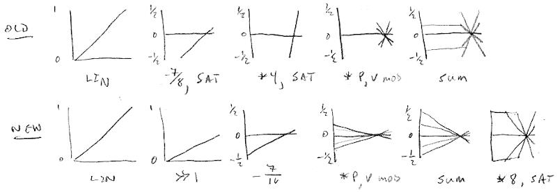
Ah, the billion days spent re-reviewing pitch and volume axis modulation have finally paid off!  It has occurred to me that the -24dB / 440Hz pivot point is a "one size fits all" that really doesn't.  Well, it works fine for the pitch side, but -24dB is just too far down on the volume side for the modulation to not get lost in the accompanying volume reduction.  This morning I tried pivoting the volume axis instead at 0dB and, wow, it allowed me to simplify a bunch of basic stuff:


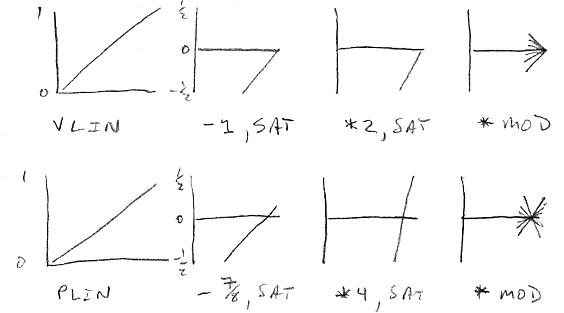
Above shows the processing graphically.  The linear axis numbers are on the left (32 bits = 192dB of dynamic range). 

Bottom: For the pitch axis, it's the same old -7/8 (440Hz), saturation (+/-1/2), *4, saturation, and mod multiplication, which gives us an input range of 48dB mapping to an output range of 96dB as +/-48dB, with an overall gain of 2. 

Top: For the volume axis, the linear volume number has 1 subtracted from it, which positions the entire thing below zero, then saturation (0,-1/2), *2, saturation, and mod multiplication, which gives us an input range of 48dB mapping to an output range of 48dB as +/-24dB, with an overall gain of 1.

The pitch output is divided by 2, added to the volume output, *2, and saturated, which gives the equivalent gain of 2 to both axes.  (Not necessary, but seems to work fine.)

So I can now make harmonic content / filter cutoff / oscillator crossfade / etc. happen much more abruptly near maximum volume.  And I was able to get rid of negative offset ranges to these nominal knobs.  While I was in there I reduced all xmix ranges to [0:31], which makes them less "spinny" in use.  When volume modulation is positive the nominal knob now sets the maximum, and when volume modulation is negative the nominal sets the minimum - really pretty convenient, and a lot less back and forth.  I was hung up on the modulation knob moving things in the positive / negative direction directly, which is perhaps a bit more intuitive, but didn't really apply even to the old scheme when your hand was below the pivot point.

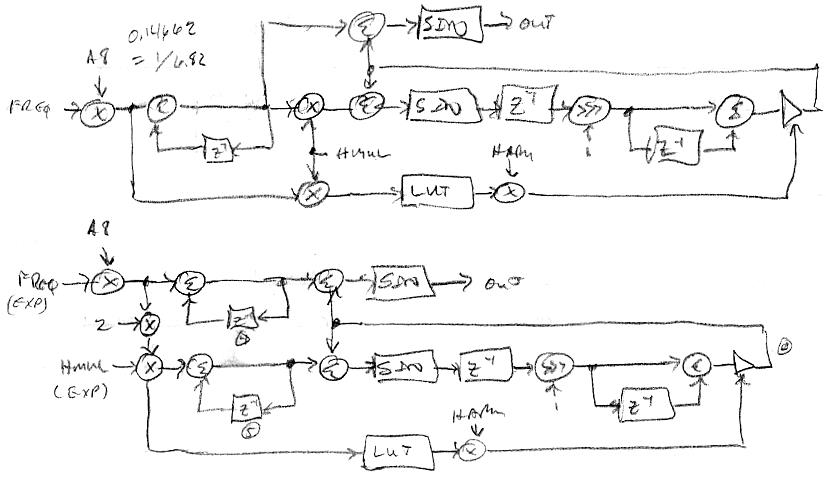
I've got rough PV_MOD working on the oscillator harmonic multipliers, but need to refine it.  I can feel the end of the D-Lev SW effort nearing ("I'm coming, Elizabeth!").  It uses 93% of main memory, and maybe 80% or so of real-time, so it fits like a glove in the Hive processor.  I'm quite pleased with it all.  This is a GIANT project (made giant-er because Hive), though once the myriad of basics have been nailed down, a v2 spinoff might actually be more of a baby / child step.

Posted: 4/5/2020 7:26:50 PM
dewster

From: Northern NJ, USA

Joined: 2/17/2012

PV_MOD - Final!

Just finished overhauling everything that uses pitch and volume axis modulation.  The hinge point makes all the difference!  For normal use I'm hinging the volume axis at 1=0dB and the pitch axis at 7/8=440Hz (as described in my previous post).  For the harmonic multiplier the volume axis hinge point is 7/8=-24dB.  For noise PWM the pitch axis hinge point is 3/4=24.5Hz.  Also for the noise PWM I got rid of the negative pitch axis modulation, as one either wants the pulse width proportional to the cycle time (pmod=0), constant (pmod=32), or somewhere in between (though pmod goes to 63).  The modulation and nominal controls make more intuitive sense now, and interact a lot less, and some knob ranges have been reduced without hurting anything.  There could be a bit of touch-up on the harmonic multiplier modulation down the road, but that's probably about it.

Another basic thing addressed: All oscillator phase accumulators are now zeroed @ preset load, and I removed all other NCO zeroing logic.  You need phase alignment for repeatable / reliable timber generation when mixing the oscillator outputs (e.g. all + odd) if one is using integer harmonic multipliers, and this is one way of doing it.  I should make the filters damp at preset load too, to stop all the "boinging" when switching to highly resonant presets.

I'm thinking about the Subscope "velocity" knob again, particularly since JPascal was recently able to replicate the behavior.  It seems like maybe it's just a high pass filter (on the exponential side) added back in, with some gain?  The knob is a gain control, and the high pass cutoff frequency is fixed?

Posted: 4/5/2020 8:09:03 PM
pitts8rh

From: Minnesota USA

Joined: 11/27/2015

"It seems like maybe it's just a high pass filter (on the exponential side) added back in, with some gain?  The knob is a gain control, and the high pass cutoff frequency is fixed?" -Dewster

Bingo!

You must be logged in to post a reply. Please log in or register for a new account.