Let's Design and Build a (mostly) Digital Theremin!

Posted: 7/22/2019 7:12:31 PM
dewster

From: Northern NJ, USA

Joined: 2/17/2012

"dewster, dont worry, we are all the men in years, with an upper bound of 10-12 kHz"  - ILYA

Ha!  Yes, sadly true.  Particularly lately, as my left ear has some kind of middle ear fluid buildup from summer allergies, killing what HF response there is left. For some reason, losing part of one ear's response seems worse than losing 1/2 of one's entire hearing ability.  But I worry about the younger set hearing things I don't, or expecting things that aren't there.  Like when I went to live rock concerts as a youth, the mixing guys were all HF deaf due to over-exposure, so they boosted the treble like a maniac to compensate - really unpleasantly harsh to listen to, and I don't want to be that guy obliviously dolling out poor sonic experiences.

"In my filtering spreadsheet I'm seeing anything significantly above ~4kHz not behaving all that "scientific".  High Q peaking gets really droopy, and the center frequency of the peak is significantly in error.  For example, setting it for 7kHz and infinite Q (damping = 0) I see a ~6kHz peak of only a couple of dB.  So if we made the top frequency 8kHz the entire top octave would have increasing error as the setting approaches the top." - me, above

There must be something wrong with my spreadsheet sim as I just converted all the filters to A8 max and they're working like champs with gobs of Q even at A8 (7040 Hz), and Audition tells me that the resonant frequencies are dead nuts to what is displayed on the LCD.  There is one double detent frequency at 29Hz, but who cares.  Now to convert the oscillators, the tuner, and the pitch correction (and all of the presets...).

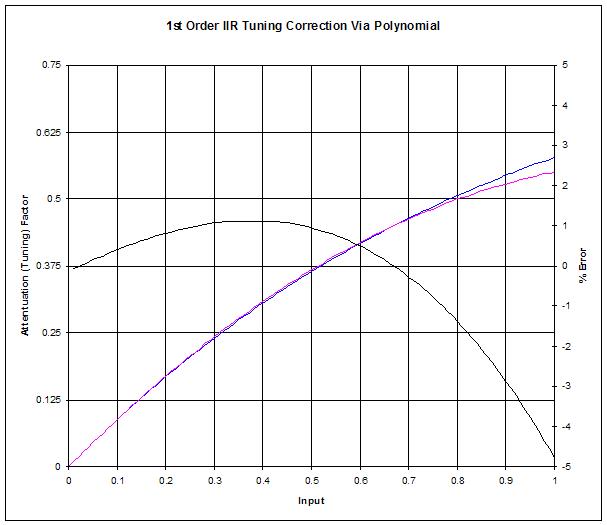
[EDIT] All done with the SW edits!  The filter polynomials needed jiggering, as did the oscillator anti-alias polynomial, thought the oscillator anti-alias LUT was fine as-is (thank god). The oscillator frequency scaling need a touch-up, as did the tuner offset.  It was considerably easier than I thought it would be, but everything is pretty modular at this point.  Made a table in Excel to assist with old => new filter frequency conversions, just need to apply it to my presets and back them up to my PC.  The lower octave going down to ~16Hz was fairly useless (so good riddance), and the extra ~3kHz of headroom for formants and oscillator operation is quite welcome.  It's this fundamental stuff that is totally worth revisiting when the overall design feels like it's wrapping up.  I'm running out of issues to address, and I suppose that's a good thing, but it means I need to refocus my efforts to cabinetry and developing more presets.

Posted: 7/24/2019 7:52:11 PM
dewster

From: Northern NJ, USA

Joined: 2/17/2012

Inharmonic Resonator Modes Update

Was messing with the resonator in one of the presets yesterday and got confused about exactly how the four modes were assigned.  Confusion is bad, particularly since I wrote the thing, so I took another look at it to see if the situation could be improved.  I decided to go from a [0:3] knob to a [-2:2] knob and use the +2 and -2 positions as stereo.  At first I assigned bypass to the 0 position, but this morning I realized there was an opportunity to utilize the crossfade xmix control for the formants that I wasn't taking advantage of.  Here is the datapath after the latest code edits:


And here are the current mode assignments shown in a more schematic fashion:

I think having +2 and -2 doing the two stereo modes is fairly intuitive.  

Negative modes place the resonator in series with the formant filters, so the resonator is acting more like an ambience reverb, with the xmix knob controlling wet / dry mix.  Negative modes can also be used for bells and such that employ just the resonator with a lot of feedback.  

Modes 1 and 2 place the resonator in parallel with the formant filters, which we use for things like the cello voice.  Here the xmix knob controls the formant / resonator mix.

Mode 0 is a parallel mode that bypasses the resonator (and the high pass filter as well), but allows the xmix knob to control the global xmix of the formant bank, much like the xmix knobs work for the oscillator and noise filters.

When the xmix control is set to 0, the inharmonic resonator is fully bypassed, regardless of any other knob settings.

While I was in there I converted the high pass filter frequency knob to the type used for the formants.  I'm quite happy with the resonator at this point.

Just did another type inventory, there are whole swaths of unused groups I'm contemplating removing.

Posted: 7/25/2019 9:02:18 AM
pitts8rh

From: Minnesota USA

Joined: 11/27/2015

Do you remember where you bought the S/PDIF decoder shown in one of your previous posts?

http://www.thereminworld.com/forums/T/28554?post=215481#215481

It appears to be of much higher quality that the random decoders that I have been getting (blue/white solder mask with unlabeled ICs).  I think I've ordered mine (twice) from the original link that you gave me (Amazon or eBay)

Posted: 7/25/2019 11:51:53 AM
dewster

From: Northern NJ, USA

Joined: 2/17/2012

"Do you remember where you bought the S/PDIF decoder shown in one of your previous posts?" - pitts8rh

Had to go back to my 2014 emails because eBay has extremely spotty order history:

https://www.ebay.com/usr/xuusastore/

This is actually something I was thinking we might discuss.  Going from PCM to SPDIF in the FPGA, and then going from SPDIF to serial PCM to analog in a cheesily made outboard box is rather roundabout if you are contemplating laying out and soldering up your own DAC circuitry.  I don't have any particular DAC in mind, but you might be able to find a quad DAC in a single package that would require a few FPGA connections (bit clock, word clock, serial data - or similar) and then buffer the outputs via opamps to line out and headphone out.  I could code up the appropriate FPGA logic, and it would skip the SPDIF middle man altogether.  IIRC the analog gain of the buffers in the SPDIF box I have is too high, which causes internal clipping and wastes SNR coming from the DAC.

Posted: 7/30/2019 8:57:05 PM
dewster

From: Northern NJ, USA

Joined: 2/17/2012

Building A Better Mousetrap Volume Control

Donations from a small local estate filtered their way through casa del dewster last week, which included many small hand bells.  I recorded various ones and tried my hand at synthesizing them on the D-Lev, thinking that might make a nice TW post, and could lead to some presets.  This led to a rescaling of the filter damping knobs to have more resolution on the "ringing" end of things, which led to a rescaling of the volume / level functions, which led to a minor overhaul of the type system, which lead to a set of generic offset exponential types that go to zero on the low or high end, which entirely supplanted all of my power based-parameters so I ripped them out.  For instance, here is the old squaring based volume control response:


One interesting thing about the old response is that it's down 12dB for every halving of the detents.  That might seem good because it gives finer steps on the business end where it's louder, but it's actually kind of a problem because the steps there are around 0.27dB.  We can hear ~1dB changes, so that's a little too fine.  It does drop off to true zero (negative infinity dB), so you can completely shut up whatever it's controlling, and the steps near zero can be as steep as necessary in order to do this.  But it would be better to space out the changes more in line with the resolution of the ear.

What we really want is more like this:

Here the steps are an almost constant 0.8dB or so until they hit the halfway point (detent 32), then they slowly increase to 1dB down to 1/4 (detent 16), after which they fall off to zero in a smooth and orderly fashion starting around 1/8 (detent 8).  The way to generate this function is to multiply and offset the encoder value, do an EXP2 (2^x) and then subtract the residual value you get for zero input.  Depending on the multiply and offset you can generate any dB change you like, I picked increments of 24 for my types: 24dB, 48dB, 72dB, and 96dB.  Not a lot of use for 24dB, but the others are handy.

This family of knob scaling types has replaced virtually all of my power-based knob scaling types, to the degree that I ripped those out.  Filter resonance settings are much more uniform now, as are volumes and other levels, and the inharmonic resonator feedback.  Of course this has discombobulated all of my presets, so I need to go through them and fix things.  I generated a series of tables that will aid in the effort.

Power-based knob scalings work pretty great when you're first starting out, and can almost see you through to the end if you're not too picky.  But EXP2 knob scalings are better suited to most situations that you'll encounter in musical instrument DSP.  Which makes sense, natural things are almost always linear, logarithmic, or exponential.  Most of these calculations are done on thread 7 in non-real-time, but a very low resolution EXP2 (non polynomial) can be done in as little as 7 cycles, so they're not super expensive code-wise or time-wise.

With this, my search for the optimal volume control has resolved, as have many, many other scaling issues.

Posted: 7/31/2019 3:01:22 AM
dewster

From: Northern NJ, USA

Joined: 2/17/2012

Building A Slightly Better Resonator

Yet more changes (*sigh*) to the inharmonic resonator:


Previously I had the cutoff frequency of the low pass filter tied to the level of resonance.  Now I've got it tied roughly to the resonant frequency of the overall comb.  I added a crossfade to the low pass filter output that's tied to the level of resonance, so the 100% infinite feedback setting goes around it.  The crossfade scaling is not, cube, not to emphasize the bypass path, the lowpass cutoff scaling is EXP2 48dB, polynomial to more or less track the comb.  The feedback gain Km scaling is reverse, EXP2 96dB, not, to heavily emphasize feedback very close to +/- 1.

Nothing earth shattering in terms of sonic difference, though high frequency settings can "ring" better and with finer control over the decay time, and the whole thing now feels less ad-hoc.

[EDIT] Twist of fate: it turns out that it's better to control the crossfade with the frequency knob, and the lowpass cutoff with the resonance knob - and both simply linear!  The LPF needs to back off at higher frequencies to provide sufficient sustain at higher resonance (higher feedback) levels there, and moving the LPF up with resonance seems to align with actual physics and sound more natural.  So, initially fairly counter-intuitive, but in the end understandable.  Tons o' sonic nuance to be ferreted out and dealt with.

Posted: 8/1/2019 6:14:17 PM
dewster

From: Northern NJ, USA

Joined: 2/17/2012

With Bells On

Tried my hand at synthesizing some bells on the D-Lev:

You can listen to them here: [MP3].  The real bell is first, followed by the synth bell.  Recorded in this order:

1. Glass bell (the red one in back).
2. Small brass bell (foreground).
3. Medium brass bell (center).
4. Telephone bell (left).
5. Elephant bell (right).

It's hard to get the excitement sound right, and real bells tend to have low frequency beating going on that I couldn't really address.  The elephant bell was a bear as it has really complex harmonics that I could only very roughly approximate.  Still, it's kinda fun.

[EDIT] I should add: The way I approach bell synthesis is to examine the spectra of the bell in Audition and set the D-Lev formants to the relative frequencies and amplitudes, with the inharmonic resonator providing some top end complexity and pseudo stereo.  Simple bells generally don't have a lot of resonances, though the resonances they do have are generally at non-harmonic ratios. 

So what would an A minor bell sound like?  Here are three of them! [MP3].

Posted: 8/2/2019 4:36:08 PM
dewster

From: Northern NJ, USA

Joined: 2/17/2012

First Order IIR Compensation

Here is my latest spreadsheet for polynomial correction of 1st and 2nd order IIR filters based on maximum note A8: [LINK].

It's kind of weird that Chamberlin didn't give an exact formula for the cutoff frequency of a 1st order IIR low pass filter in his book.  I finally ran across the formula the other day here: [LINK].  I understand the derivation, and it checks out with my simulations.

The exact cutoff (-3dB) point of a first order IIR low pass filter for a given attenuation (tuning) factor is:

  wc = acos( ( a^2 + 2a - 2 ) / ( 2a - 2 ) )

where wc = 2 * pi * Fc / Fs, so:

  Fc = wc * Fs / ( 2pi )

Going the other way, the exact filter attenuation (tuning) factor for a given cutoff frequency is:

  a = cos(wc) - 1 + sqrt( (cos(wc))^2 - 4cos(wc) + 3 )

Simple multiplication by 2*pi*A8/Fs gives maximum error of 59% located at maximum input/output.


Above graphically the 1st order case, the blue line is the perfect attenuation factor, the red line is the polynomial approximation, and the black line is the %error between the two.  I pushed most of the error towards the high end.  First order low pass IIR filters are really mushy, the exact cutoff point is audibly indistinct, the high pass cutoff significantly deviates from the low pass, and they massively poop out heading towards Nyquist, so it generally doesn't pay to get too scientific on them.  Whereas 2nd order SVF filters can be quite exact, particularly when the Q is high.

A two term polynomial (^1 and ^2, with the ^0 term = 0) works fine for the first order LPF.  A two term polynomial (^1 and ^3, with the ^0 and ^2 terms = 0) nets you +/- 0.005% for the second order SVF.  So none of these calculations are particularly expensive.

Posted: 8/5/2019 5:51:49 PM
dewster

From: Northern NJ, USA

Joined: 2/17/2012

Antenna Types & Connections

I'm currently on vacation, but can't give this place up!  Getting away always seems to free my brain up from the well-worn paths it takes every day at home.

Anyway, I'm going to do an experiment when I get home regarding plate antenna composition.  I'm wondering if a mesh or screen might work as well as a solid plate, and if the mesh works well enough with large holes, maybe even a loop of pipe might be as sensitive?  This is one of those "basic experiments" which would be nice to know the answers to.  I'm surprised I didn't think to do it until now.


Don't have a scanner with me, so these are pics taken of my notebook, manipulated in Gimp (which I'm trying out seriously for the first time).  I think the experiment could be as simple as constructing the various antennas and measuring their intrinsic C via my resonating LC meter.  Or I could rig up a connection to one of the D-Lev axes and measure the resonance frequency, and work back to C via the LC equation.  For identical form factors, I believe intrinsic C is proportional to mutual C.

A screen or tube type arrangement wouldn't obscure the player to the audience as much as a solid plate would.  A tube might look the coolest.  With the volume horizontal and the pitch vertical, it might look like Robbie the Robot ears!

As for overall form factor, for me and my (non) playing style at least, I think I want it to be square as shown above.  A square would keep my pitch hand closer to the tuner for better targeting, and the sweet spot should be wider in both axes than compared to a circle or rectangle.

=============

Also pondering at which juncture to electrically connect the antennas to the D-Lev tour case.  Here are the options:


Going from the fewest connections on the left to the most on the right:

1. Connecting the antenna to the business end of the coil is the most straightforward and only requires one electrical connection, but is problematic because the connection point is very high impedance.  Also, any metal here can look like a magnetic core or shorted winding to the coil.
2. Connecting after the coil requires two connections, one low impedance and one medium impedance, and places the 1pF component of the C-divider on the coil side. 
3. Connecting after the C-divider requires three connections, two low impedance and one medium impedance.  This arrangement is particularly interesting because the C-divider can be tailored to the Q of the particular coil and antenna combination once and for all, making the combo freely interchangeable with others.
5. Connecting after the AFE3 requires 5 connections, which is a lot, but they are all low impedance.  But then you have to find room for the AFE somewhere.

I'm leaning towards 2 or 3 at the moment.  It really all depends on what is available / manufacturable.  Either the connection between the antenna and coil, or between the coil and the cabinet, would have to be able to freely rotate so as to position the volume plate horizontally and the pitch plate or rod vertically.

[EDIT] I should have included one more possibility, located between the antenna and the 1pF capacitor, which would require two connections, one low and one very high impedance.  This would place the entire C-divider inside the cabinet, but again the high impedance is problematic.

[EDIT2] Now that I think about it some more, one could "standardize" on 100pF in the C-divider and vary the 1pF based on the Q of the coil / antenna combo, giving one interchangeability with the two connection case.

Posted: 8/5/2019 6:21:38 PM
dewster

From: Northern NJ, USA

Joined: 2/17/2012

D-Lev tour (the continuing saga...)

Sketching again.  Placing the coils inside the D-Lev tour wooden cabinet would expose them to a lot of C due to the wood, guts, and connectors at point 1 in the previous post.  The volume coil in particular would be placed very close to the player's body, which seems like a bad move.  The volume coil would also likely preclude using the angled bottom end of the cabinet for I/O connections, and that is some precious real estate IMO.  So the coils should probably go outside the cabinet, and be integrated into the antennas.  I think the AFE3's could / should be inside the cabinet though.  Here's my latest thinking:


The above shows square "fly swatter" antennas on both volume and pitch - square (though not necessarily mesh) would be my personal preference for me, others could have whatever they like here.  Having the pitch antenna closer to the tuner will likely improve my playing a bit as that will allow me to keep a better eye on both at the same time.

You must be logged in to post a reply. Please log in or register for a new account.