Let's Design and Build a (mostly) Digital Theremin!

Posted: 1/20/2020 9:21:02 PM
dewster

From: Northern NJ, USA

Joined: 2/17/2012

Librarian (done?)

Made a lot of progress yesterday, and I think it's mainly done for now.  Here's a video captured via Kazam (really nice simple Linux software) no audio:


0:00 The opening screen, showing serial port opening OK.
0:02 The preset editor screen, showing highlight mode.
0:06 The file list directory screen, showing highlight mode.
0:09 The slots screen, blank until you download some slot data from the D-Lev.
0:11 The Terminal screen, here you can communicate directly with the D-Lev Hive Command Language (HCL) over the serial port.
0:13 Directory screen, I use the tab-based auto-complete to load the accordion preset file.
0:18 Editor screen showing the accordion preset knob positions.  In highlight mode I can inc/dec via +/- keys, directly set the value, and of the whole page.
0:46 Directory screen, copying a file and deleting it.  The highlight + Enter copies the file name to the command line.
1:07 Slots screen, downloading different ranges, then all.  The highlight + Enter loads it to the editor and takes you there.
1:51 Terminal screen, reading registers 0-9, the SW version & CRC, all memory locations (16kB).
2:07 Editor screen, pumping the SPI EEPROM SW image.
2:32 Terminal screen, checking the SW load.

Coding the WIN32API serial stuff was fairly easy following the examples on the web.  Most of the polling timing and buffering was already worked out in Linux, which I'm sure made it a lot easier.  Had the D-Lev powered via my Win10 Lenovo el-cheapo laptop, which worked better than I thought it would.  The Win7 and Win10 consoles are really sluggish compared to the WinXP and Linux consoles, another reason to ditch MS if you're migrating from XP!

Posted: 1/21/2020 9:04:28 PM
dewster

From: Northern NJ, USA

Joined: 2/17/2012

Monkeying Around

Interacting with a literal sock puppet (for a change):

This was maybe the fifth time I'd played the piece, it's simple but I barely "know" how to play it, so: sorry, and be kind!  The toy plays everything back from up to the last six seconds an octave higher than recorded.  Laughter sounds particularly insane!

Found incredibly nice webcam video capture software for Linux: GUVCView.

Posted: 1/22/2020 11:19:14 AM
Buggins

From: Porto, Portugal

Joined: 3/16/2017

Interesting cheap enough chinese Xilinx Zynq FPGA board for $55.9
   https://www.aliexpress.com/item/4000323573953.html?spm=a2g0v.12010612.8148356.1.6f1bb6dfLJBaYn

Twice cheaper than Digilent Cora Z7 on the same 7Z010 chip.

SOC:
Dual core ARM
512MB of DDR3 SDRAM (although it's slow enough due to 16bit interface).
A lot of available pins: 40+50pins connectors
FPGA: 28K logic cells, 2.1MBit BRAM

Complicated GUI related functionality may be done on ARM, leaving a lot of resources of FPGA logic.

Mini USB cable can be used for programming.

Ethernet connector - not sure if can be useful for theremin


Posted: 1/23/2020 2:28:36 AM
dewster

From: Northern NJ, USA

Joined: 2/17/2012

"Twice cheaper than Digilent Cora Z7 on the same 7Z010 chip."  - Buggins

That's an amazing load of processing there!  If this project ever makes it past the first manufacturing phase I'll definitely be on the lookout for more like that.

Posted: 1/23/2020 6:05:51 AM
Buggins

From: Porto, Portugal

Joined: 3/16/2017

dewster,

Are you using DAC with sigma-delta modulation directly implemented on FPGA?
What is its sound quality? Did you try to measure harmonics and noise level?
Is it comparable to external I2C codec?

Are you passing FPGA pin output directly to LP filter?
What about buffering (with buffer powered by separate voltage regulator) to get less noise?

I'm trying to figure out what is better, using FPGA out + LP filter on opamp (+ power amplifier for headphones) or just connect some I2C codec board where analog part is already well done.

Posted: 1/23/2020 1:31:13 PM
dewster

From: Northern NJ, USA

Joined: 2/17/2012

"Are you using DAC with sigma-delta modulation directly implemented on FPGA?"  - Buggins

I struggled with this for a long time.  You can certainly code up a sigma-delta modulator in the FPGA, a second order modulator is pretty easy to implement and inherently stable, though it will have modes.  For higher orders MASH is doable but would require more pins and I believe a more precise external D/A.  And the higher order you go the more demands there are on the external low pass analog filter, it has to have an order higher than the modulator in order to roll off the modulation noise.  Regardless, whatever digital noise there is on the FPGA bank supply will directly transfer into the audio, so you need to do differential (harder to filter and deal with in general) or translate the digital signals to quieter supplied logic before doing the single or multiple bit D/A and LPF.

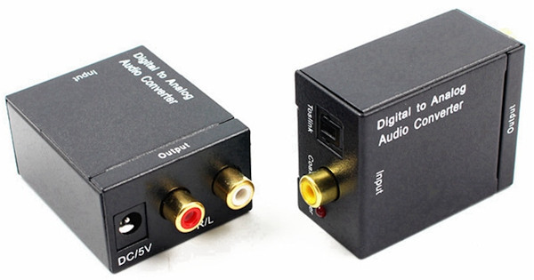
In the end I coded up a System Verilog SPDIF TX component in the FPGA.  The data source is two 32 bit Hive processor registers, the clock source is a cascade of FPGA PLLs which also provides the 48kHz interrupt to the processor, so it's all synchronous.  The SPDIF output goes to one of those inexpensive SPDIF to RCA DAC boxes (I got mine via an auction on eBay for almost nothing):

I thought it was necessary to use the optical Toslink connection to keep serial noise low, but Roger found the electrical SPDIF connection is equally fine in terms of noise, so that's how we're driving it now.  Just one FPGA pin.

It's the simplest way I've found to get a clean analog signal from FPGA PCM.

One thing to watch is to never fully zero out the SPDIF data for any length of time or else the box will mute itself, and it can take a bit of time to come out of the unmuted state.  Also, the box clips the analog signal before reaching 0dB digital, so you have to give it some headroom.

Posted: 1/23/2020 3:49:15 PM
dewster

From: Northern NJ, USA

Joined: 2/17/2012

As Time Goes By [MP3]

Posted: 1/24/2020 11:42:33 AM
Buggins

From: Porto, Portugal

Joined: 3/16/2017

To minimize digital noise, buffer powered from separate 3.3V regulator can be used.


What is SPDIF transmitter module you are using? Is it optical out module?

Posted: 1/24/2020 2:47:10 PM
dewster

From: Northern NJ, USA

Joined: 2/17/2012

"To minimize digital noise, buffer powered from separate 3.3V regulator can be used."  - Buggins

True.  But the SPDIF box isolates everything and gives a super clean signal with plenty of SNR.  There's a fair amount of engineering going on in DACs these days, some features (like the auto mute) aren't necessarily desirable, but most are, and can really reduce your engineering effort.  I'd love to have most of the DAC inside the FPGA, but it was just too much.

"What is SPDIF transmitter module you are using? Is it optical out module?"

Yes, some optical SPDIF TX modules I bought surplus, they have a little amplifier inside to unload the input pin.  But you can just drive the SPDIF box directly with an FPGA pin via the SPDIF box RCA input jack with no loss in audio quality.  The box will probably be powered by the Theremin anyway, so the electrical isolation you would get from an optical connection doesn't necessarily gain you anything (except maybe elimination of ground loop if you power the SPDIF box with a laptop or something).

Posted: 1/25/2020 7:43:07 PM
dewster

From: Northern NJ, USA

Joined: 2/17/2012

4th Order Cook

I found a minor bug in the 4th order state-variable filter (SVF) as implemented on the D-Lev.  There is a cross-mix knob that controls bypass of the filter, and I was using the attenuated first stage output for bypass rather than the unattenuated version.  Very simple fix, but of course I just had to have another look at what was going on.  And of course two days later I'm almost completely back to where I started, except for a simple but very important change.

I decided a while ago not to attenuate SVF filter input based on the filter damping setting.  DSP textbooks recommend that you normalize the peak to prevent overload with various damping settings, but my feeling is this is wrong.  If you don't normalize the peak, then you get a peakier peak with decreased damping, but the overall sound energy remains fairly constant, which I think is much more important musically.  If you normalize the peak you get reduced overall gain with reduced damping, which can make it sound really thin, and then you're reaching for the gain anyway.  If you really want it to resonate then you'll have to lower the input signal to avoid clipping, something you'll be doing as a matter of course for any patch changing situation.  Peakier peaks are how natural resonators seems to operate too, where energy collects and then is lost at a given rate.

The above discussion is for the second order filtering case, or one stage of SVF filtering.  What about the 4th order case, or two SVF filters in cascade?  The cascade exacerbates the damping gain, and without some kind of gain reduction between the first and second stages it's easy to get it in a situation where the first stage is ringing and overdriving the second stage.  The gain reduction needed to do this is conveniently exactly the value of the damping.  So we take the output of the first stage, and multiply it by the damping before feeding it to the second stage.  But this presents us with a problem: how do we keep the first stage from ringing too much?  I solved this by offsetting the damping to the first stage by +1/256 (0x1000000, or -48dB) and limiting the result, which gives for an input damping of [0:1) an output of [1/256:1).  I also used this offset and limited damping value to scale the output of the first stage.  Here's a flow diagram of the result:

Above you can see the full damping is used for the second stage, but the offset and limited damping is used for the first stage damping and output attenuation.  This minimizes internal overload and gives the 2nd and 4th order filters equal peak gain.  It works really well!  The selection of 1/256 as the offset seems to be rather arbitrary, as 1/16 (-24dB) works well too.  I went with 1/256 because -48dB is roughly the threshold of silence, and when you're lowering the damping of the 4th order filter you see the skirts diving down to the noise floor (due to the attenuation going on at the output of the first stage), so why not more or less align the silencing action with silence?  Here's a movie I made of the the filter in action:

I'm using the fantastic program "Friture" to display a real-time FFT (just download the AppImage "blob" and run it) along with "Kazam" to capture the window on my Linux Mint desktop.

0:00  white noise
0:04  2nd order HP (high pass), reso=0
0:07  2nd order BP (band pass)
0:11  2nd order LP (low pass)
0:16  4th order HP
0:20  4th order BP
0:25  4th order LP
0:35  2nd order BP
0:40  reso=20
0:46  4th order BP
0:55  reso=30
1:00  2nd order BP
1:10  reso=40
1:20  4th order BP
1:34  gain reduced
1:40  reso=55
1:48  2nd order BP

You can see and hear in the video that the peak increases with reduced damping (increased "reso") and that the "peak of the peak" is the same for the 2nd and 4th order cases across a wide range of damping.  You can also see the filter skirts dip based on damping in the 4th order case, but the 2nd order skirts are more or less constant with damping.  As it only operates on the ultra-resonant fringe of the 4th order case, this change shouldn't affect any of my current presets.

You must be logged in to post a reply. Please log in or register for a new account.