Let's Design and Build a (mostly) Digital Theremin!

Posted: 2/25/2020 4:25:31 PM
dewster

From: Northern NJ, USA

Joined: 2/17/2012

Noise & Bit Growth

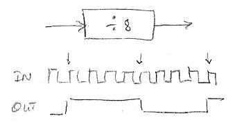
Pic from my post above on axis number acquisition:

You can see that we start out with tons of bits from the DPLL NCO, but if we examine the bits when the system is stable, we find that a whole lot of the least significant bits are changing quickly when nothing is otherwise going on, and therefore not very useful.  Simply truncating the noisy bits away leaves us with too few bits for musical purposes, and gives a step-like or "zippery" non-smooth response to our hand movements.  What to do?

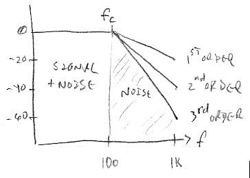
If we look closer at the unstable bits, we see that much of the bit flipping is happening really fast, in other words the noise has strong high frequency content.  And we know that our senses will tolerate down to ~100Hz (or perhaps even less) of gestural bandwidth before noticing anything is awry (laggy, slow, delayed, etc.).  So the first obvious move is to stick a 100Hz low pass filter on there, which allows our gestures to get through, unfortunately along with any noise in the 0Hz to 100Hz passband, but more importantly lops off the noise above 100Hz, and we discover that at the output of the filter we've got quite a few more stable bits to work with.  Yay!  Can we do better?

This may sound self-evident, but it took me forever to come to grips with conceptually: noise reduction is really all about reducing the area of the frequency response where the noise resides (duh).  If your lowpass filter is first order, then the noise above the cutoff frequency will be attenuated at a rate of 20dB / decade.  For a first order filter set to 100Hz, at the 10 times higher frequency of 1kHz the response is reduced by a factor of 10, or -20dB; the response at 100 times the cutoff frequency or 10kHz is reduced by a factor of 100, or -40dB, etc..  It's a simple 1:1 slope (when graphed log:log, and which I never learned in school).  This downward sloping attenuation region above the cutoff frequency is known as the filter "stopband" or "skirt" and it is the area underneath the skirt which is letting in the noise.  If we can increase the skirt slope we will reduce the area below the skirt, thus reducing noise without affecting our signal.  The way to increase the skirt slope is to to employ a higher order filter, and this can be as simple as cascading first order filters.  For each increase by one in the filter order we increase the skirt slope by -20dB / decade, so a second order filter gives us  a -40dB / decade, a third order gives us -60dB / decade, etc.

If we stick a second first order lowpass filter after our first one we notice at its output that more bits are now stable, but the number of stable bits we've gained isn't nearly as dramatic as what our first filter gave us.  Sticking a third first order lowpass filter after the second provides us with an even smaller increase in stable bits, so we've clearly entered into diminishing returns territory.  Our first mild filter gave us a big bit gain by massively reducing the noise bandwidth, the subsequent filters bit gains were smaller and smaller because all they could do was fractionally decrease the noise via skirt area reduction. 

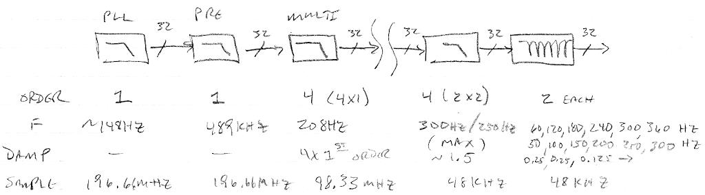
And as detailed in the post above, the filter order I ultimately picked for this filtering was based more on alias control at the rate changing interfaces than based on bit noise improvement.  Though I of course employed the acceptable lowest gestural bandwidth limit of ~100Hz to start the skirts as soon as possible, and thus maximize the anti-aliasing action and bit noise reduction, and minimize the number of filters required.  (I should also mention that cascading filters tends to lower the overall cutoff frequency of the result, so the individual cutoffs must be adjusted up somewhat, hence my use of 148Hz for the DPLL cutoff, and 208Hz for the "multi" filter cutoff above.)

In software, the variable 4th order lowpass filter does a bit of smoothing on our 48kHz down-sampled data, but more importantly squashes any 60Hz / 50Hz mains hum harmonics above the cutoff frequency, and this allows us to use fewer notch filters to clean up the remaining harmonic noise.  Things are arranged so that the 4th order cutoff frequency is reduced proportional to the hand movement away from the antenna, thus squashing noise even more in this region of operation.  This is clearly at the expense of gestural bandwidth in the far field, but the effect isn't obvious, and the far field kind of sucks anyway from a playability perspective on any Theremin due to a variety of issues (long-term null accuracy and therefore linearity due to drift, body movement, etc. and on analog Theremins there is often further non-linearity due to oscillator coupling).

Finally, there are local interferers to deal with.  I found the regular LCD updating was injecting a 12Hz spike into the axis response, so I changed the code to only update it when there was an on-screen data change and the spike disappeared.  The LED tuner update is done at 48kHz which would likely be mostly filtered away, but just to be safe I made the PWM pseudo-random rather than counter-based, and I also massively jittered the data going to it in a pseudo-random way.

One other thing: there was a weird "traveling hump" in the axis spectrum that followed the audio oscillator pitch.  I figure it was caused by rhythmic current draw in the FPGA core due to the NCO and filtering calculations going on to generate the audio.  Arranging things so that the variable cutoff of the 4th order filter was always below the pitch killed the hump pretty much dead.

So, there you have it.  Early on I was obsessed with theoretical ways to "grow the bits" as wide as possible.  Practically, I found that I could rely on the DPLL itself and the anti-alias sampling rate reduction filters to do most of that sort of bulk filtering.  But, in the end, mains filtering was found to be a major component of the overall noise, and special attention also had to be paid to local interferers.  I found that there was plenty of noise below the 100Hz cutoff that had to be dealt with on a case-by-case basis with special filtering / randomizing.

The D-Lev environmental filtering and local interference reduction is so effective that I'm seeing individual data steps on the LED tuner where the resolution totally poops out (at null).  Before I took these various steps at mitigation I was seeing mostly noise there.  I wish I could have known up-front that noise reduction is much more important than increasing the resolution via averaging, I could have easily shaved a year or two off of my investigations / efforts.  Resolution by itself isn't useful without effective noise reduction, and resolution will just "happen" if you start with a reasonable number of bits and do routine filtering.  And the extreme far field (0.6m to 1.0m) is kinda crap no matter what you do, and nobody plays there anyway (not with any precision), so it's not worth obsessing over.

Posted: 2/25/2020 6:27:45 PM
Buggins

From: Porto, Portugal

Joined: 3/16/2017


Finally, there are local interferers to deal with.  I found the regular LCD updating was injecting a 12Hz spike into the axis response, so I changed the code to only update it when there was an on-screen data change and the spike disappeared.  The LED tuner update is done at 48kHz which would likely be mostly filtered away, but just to be safe I made the PWM pseudo-random rather than counter-based, and I also massively jittered the data going to it in a pseudo-random way.

One other thing: there was a weird "traveling hump" in the axis spectrum that followed the audio oscillator pitch.  I figure it was caused by rhythmic current draw in the FPGA core due to the NCO and filtering calculations going on to generate the audio.  Arranging things so that the variable cutoff of the 4th order filter was always below the pitch killed the hump pretty much dead.

Very interesting.
How do you think, will filtering on VCC line of oscillator connector help to reduce interference from digital part? Is RC filter on oscillator board enough? 
Ferrite + C from main board side near oscillator connector? Separate voltage regulator?
Will placing of inductor and oscillator board far from main board, close to antennas help?
What about putting main board into shielded cabinet (metal box?). Distance from small cabinet box to antennas is planned to be about 12cm each.

Posted: 2/25/2020 6:45:51 PM
dewster

From: Northern NJ, USA

Joined: 2/17/2012

"How do you think, will filtering on VCC line of oscillator connector help to reduce interference from digital part? Is RC filter on oscillator board enough?
Ferrite + C from main board side near oscillator connector? Separate voltage regulator?"  - Buggins

My AFE's have separate regulation, though the FPGA pins themselves are probably jumping around a bit due to internal current fluctuations.  This stuff is so tender that it could be coming from anywhere.

"Will placing of inductor and oscillator board far from main board, close to antennas help?"

I'm doing this too, and it probably can't hurt.

"What about putting main board into shielded cabinet (metal box?). Distance from small cabinet box to antennas is planned to be about 12cm each."

You might still experience conducted emissions, from the wires connecting the stuff inside box to the stuff outside.  But again, it probably can't hurt.

The way to diagnose this stuff is to make a special SW load that 4th order high pass (~10Hz to remove DC) filters the pitch axis numbers and spits it out as audio.  Then you can use audio SW on your PC to look at the data and do real-time FFT.  This is how I caught the "traveling bump".

You do what you reasonably can do up-front to ward off trouble (voltage regulation, keep sensitive stuff away from noise, etc.) then track down the special cases once you've got it all working.

Posted: 2/25/2020 8:33:55 PM
tinkeringdude

From: Germany

Joined: 8/30/2014

That whole piano recording doesn't sound too bad, jumping through it, only on my plastic PC speakers though.
More towards the end, some of the mid/lower notes sound overly dampened (high end roll off)?

Those kind of sounds, when the lower keys attack after 3 minutes or so... my Roland just doesn't sound like that... it sounds less full somehow and more artificial, more reminiscent of my soundfont days.
But I have a suspicion that the velocity curves coming from its more synth-optimized keyboard may ruin some of it, IIRC even the software piano sounded worse when it was driven by that, vs. a MIDI controller with full weight keys / hammers.

.otherwise we could have absolutely killer, lush, nuanced digital piano voices even in low-end $500 instruments, and my own damn testing showed that there was nothing like that even on the highest end.

I was cured of such notions (well, not really, but gained awareness) after I looked at the prices of guitar loopers and estimated what would roughly be in there, especially the increase of price vs. feature set. A few stomp buttons more and some cheap software features added, let's charge those aforementioned $500 for a lower end keyboard for such a stompbox...
(Ok, I have a couple chained china loopers now, not that they're really doing everything I'd like them to )

.Though I must admit that it was a bit of a thrill informing die-hard Yamaha fanboys that their latest top-of-the-line stage piano - AS PLAYED BY SIR ELTON JOHN HIMSELF!  AT NAMM! - was audibly looped.

Maybe those pianos are more for live performances where it's not that important, and practicing.
In the studio, stuff like NI Komplete probably has you covered with gigabytes of samples.
Elton John, though... I know people who have a quiet day job and like to go to concerts a couple times a year, loud rock concerts, and who, despite being younger than me, fail to hear high whistling noises of cheap ethernet switches, chargers and stuff like that.
I imagine that Sir Elton, who was orders of magnitude more often ON stage than those people were in front of it, plus rehearsals, does himself not care much about such subtle things 

Posted: 2/25/2020 9:02:58 PM
dewster

From: Northern NJ, USA

Joined: 2/17/2012

"That whole piano recording doesn't sound too bad, jumping through it, only on my plastic PC speakers though." - tinkeringdude

Through good headphones, the middle "Brilliant" piano sounds like crap, I wish they'd stuck just about anything else in there (tack piano, etc.).

"But I have a suspicion that the velocity curves coming from its more synth-optimized keyboard may ruin some of it, IIRC even the software piano sounded worse when it was driven by that, vs. a MIDI controller with full weight keys / hammers."

I agree, velocity has so much to do with it.  There was a "shootout" web page where they ran the same MIDI file through a bunch of digital pianos and sample sets, and when the overall velocity was clearly too high for the thing (as it often was) there was almost no point to the comparison.  I adjusted the velocities down in the Satie MIDI file to bring out the subtleties and nuance of the RD-700NX.

"Maybe those pianos are more for live performances where it's not that important, and practicing."

I'm sure there is something to designing a digital piano to be "band friendly" so it "cuts through" or "sits back" in the mix.  But I think that effort could be made largely orthogonal to a high quality, high fidelity, realistically detailed piano voice offering.  But my experience is that was used as an excuse for hacked down, obviously looped fare.  And honestly, when I hear a digital piano in a band situation (or god forbid on a recording) it always sounds annoyingly fake.  I've come to loathe them, particularly when <$500 digital pianos are causing real pianos to end up on the scrap heap.  And there's nothing like the lush sound from a good instrument to encourage practice, and nothing like crap sound from a bad one to discourage it.

Posted: 2/25/2020 11:17:28 PM
dewster

From: Northern NJ, USA

Joined: 2/17/2012

Counter As Filter

I've read that a counter can be used as a filter, but it always confused me as to how that might be possible.  Here is a divide by 8 counter:


For every 4 rising edges at the input the output changes.  So only 1 out of 4 edges influence the output, and the other three could be located wherever.  If we were to somehow time the output edges we would see that this is an integrate-and-dump filter for period.  It "integrates" or sums the periods of 4 clocks before changing the output, and for every 8 clock periods in we get one clock period out.  The "dumping" is because none of the input clock periods are "recounted" or reused in any way for previous or subsequent output periods.

There was a Theremin on the web at one point, I believe it was on a Russian site?  It had a rather elaborate ferrite slug coil in the CMOS oscillator, followed by a binary ripple counter to bring the oscillation down to low audio.  This was piped into a PC soundcard where the period was measured and averaged, and a Theremin voice presumably synthesized and played with that as control.

Best case here for measurement is dividing down to perhaps 10Hz, where measuring this period with a 48kHz audio input might yield 48000 / 10 = 4800 count resolution.  This is one instance where measuring rise-to-rise and fall-to-fall would be prudent, as the signal coming out of the divider is guaranteed to be a perfect 50/50 duty cycle square wave.  This might double the resolution count to ~10,000 or ~11 bits, and it would also double the sample rate to 20Hz.  Of course a ton of these bits are useless, as the period will only change 3% or 4% or so in normal Theremin use.  So I don't think this approach is all that viable for a high quality Theremin as the gestural bandwidth would have to be abysmal for it to work at all.  But it is an interesting application of a counter as an integrate-and-dump filter.

Posted: 2/26/2020 4:01:01 AM
Buggins

From: Porto, Portugal

Joined: 3/16/2017

There was a Theremin on the web at one point, I believe it was on a Russian site?  It had a rather elaborate ferrite slug coil in the CMOS oscillator, followed by a binary ripple counter to bring the oscillation down to low audio.  This was piped into a PC soundcard where the period was measured and averaged, and a Theremin voice presumably synthesized and played with that as control.

At first time I thought it's Paradox theremin designed by ILYA. 

Oscillator gives ~7% of frequency dependency on C_hand.
After divider, frequency spread will still be 7%, e.g. 10KHz for far hand distance and 9.3KHz for near.
At 48000 sample clock, measured edge position will have 15.5 bits. +1 for both edges = 16.5 
4 upper bits are useless due to 7% changing range. 12.5 bits left.
Averaging for 64 samples gives 6 bits, but 10KHz->160Hz gives 3.3ms latency (not 6.6 because averaging gives value for middle point of frame).
18.5 bits seems playable.

As well, if signal has not too sharp edges, subsampling interpolation may be used. We have 16 or 24 bits of sampled data.
Instead of simple detection that in sample, there is 0->1 or 1->0 transition, take sample before and after transition, then calculate fractional part of edge using sample values. It should give a few more bits.

Actually, there is additional latency introduced by audio board (round trip lag = input latency + output latency + processing latency).
Low latency audio board is needed.

Posted: 2/26/2020 1:54:53 PM
dewster

From: Northern NJ, USA

Joined: 2/17/2012

"At first time I thought it's Paradox theremin designed by ILYA."  - Buggins

Looking through my files, it's the D-sensor by Andre Smirnov:

From his web pages here: https://asmir.info/tsensors_sch.htm.  The pages haven't been updated in a long time (2007) so I'm wondering what happened to him and his projects.

It looks like maybe he feeds 5kHz to the soundcard.  The coil looks like no fun to wind.  All those 4000 series CMOS in series would give a boatload of delay, likely temperature dependent.  His later designs use the same coil but only a single inverter, along with outboard bandpass amplitude detection, like the volume side of a Theremin.

"Oscillator gives ~7% of frequency dependency on C_hand."

When my hand is almost touching the D-Lev pitch plate (the pitch field is still linear there, but I never really play it that close if I can help it because vibrato would have me slapping the antenna) I'm reading 1.17MHz on the frequency counter.  With my hand and arm retracted fully to my body I'm reading 1.23MHz.  (1.23 - 1.17) / 1.2 = 0.05 = 5%.  Almost all of that is right at the antenna.  And this is a plate, not a rod antenna.  A rod would have even less sensitivity.

"At 48000 sample clock, measured edge position will have 15.5 bits. +1 for both edges = 16.5"

If you measure two edges one second apart...

"As well, if signal has not too sharp edges, subsampling interpolation may be used. We have 16 or 24 bits of sampled data.
Instead of simple detection that in sample, there is 0->1 or 1->0 transition, take sample before and after transition, then calculate fractional part of edge using sample values. It should give a few more bits."

I agree that this sort of processing, correlating a best-fit to the analog data, with data that is more amenable to this (sine, triangle) could give one better timing information than simple square edge timing.

Posted: 2/26/2020 5:11:19 PM
Buggins

From: Porto, Portugal

Joined: 3/16/2017


"Oscillator gives ~7% of frequency dependency on C_hand."

When my hand is almost touching the D-Lev pitch plate (the pitch field is still linear there, but I never really play it that close if I can help it because vibrato would have me slapping the antenna) I'm reading 1.17MHz on the frequency counter.  With my hand and arm retracted fully to my body I'm reading 1.23MHz.  (1.23 - 1.17) / 1.2 = 0.05 = 5%.  Almost all of that is right at the antenna.  And this is a plate, not a rod antenna.  A rod would have even less sensitivity.


In my LTSpice simulation with antenna C = 8pF and C_hand=0..1.5pF range, I see 7% of frequency change range.
Are you using additional C from antenna to GND? Big coil self-capacitance? Bigger antenna capacitance?


"At 48000 sample clock, measured edge position will have 15.5 bits. +1 for both edges = 16.5"
If you measure two edges one second apart...

Yes, my mistake. Not sure how I got 15.5 bits.

One period 48000/10000 gives only 2 bits.
10KHz signal, 32 periods interval averaging - 3ms total length for 32periods.
x32 interval gives 5 bits.
Additional averaging of periods with moving average FIR filter for 32 sequential edges gives 5 more bits.
Double edges give 1 bit.
Unknown number of bits may be collected with subsampling of edge position.
2+5+5+1 = 13
5% oscillator freq change eats 4.5 bits.
13-4.5 = 8.5
Everything depends on unknown number of bits from analog/dac subsampling of edge.
With 5 bits, it would be playable at 30-40cm distance.
Inceasing of latency twice should give 2 more bits == extend range by 10cm

Posted: 2/26/2020 5:32:21 PM
dewster

From: Northern NJ, USA

Joined: 2/17/2012

"Are you using additional C from antenna to GND? Big coil self-capacitance? Bigger antenna capacitance?"  - Buggins

No explicit C to ground except for 1pF for sensing.  Coils are single layer solenoid air core with good aspect ratio, so self C should be minimal.  Plate area is large so intrinsic C is large, but mutual C to the hand should be theoretically even larger - or so say my old simulations with FastCap.  IIRC a plate is somewhere around twice as sensitive as a rod in terms of % delta C.  Maybe I should move the monkey away...

[EDIT] Moved the monkey, moved the counter away from the plate, measured 1.18MHz with my fingertips maybe 1cm away from the plate; measured 1.234MHz with my hand at my side or maybe 0.6m away.  That's 4.5%

You must be logged in to post a reply. Please log in or register for a new account.