Coil & Plate Testing
I was interested in how placing a plate near a coil influences the Q of this combined LC arrangement. If too close, the plate can appear as a shorted winding, damping Q. So I selected 3 different single layer air core solenoids, and tested them one at a time while they were sitting on top of a 175mm x 175mm plate:
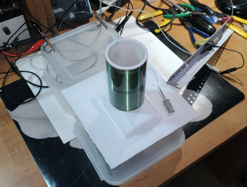
Above: 9mH coil under test. The Al foil is on the underside of the plate and electrically connected via some bus wire.
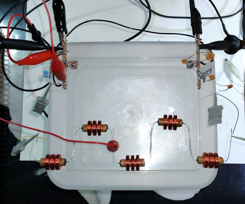
The plate consists of 4mm thick corrugated plastic covered on one side with standard kitchen aluminum foil. My test jig provides drive, which lowers the drive impedance of the signal generator to approx. 2.4 Ohms, and the output voltage of the function generator was adjusted to be 0.1Vpp at the coil drive end. Sensing was via my DIY medium voltage probe, which presents approx. 2pF load to the plate.
Spacers of scrap 4mm thick corrugated plastic were inserted between the end of the coil and the plate, and the function generator frequency was then adjusted for quadrature resonance. Scope BW limiting and averaging were used to enhance measurement of Vpp.
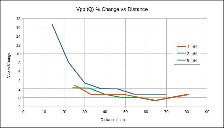
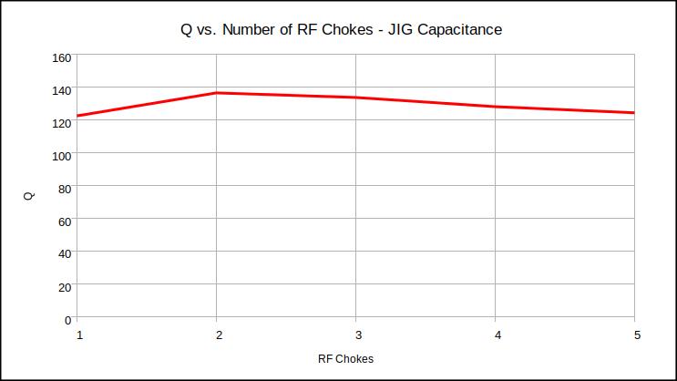
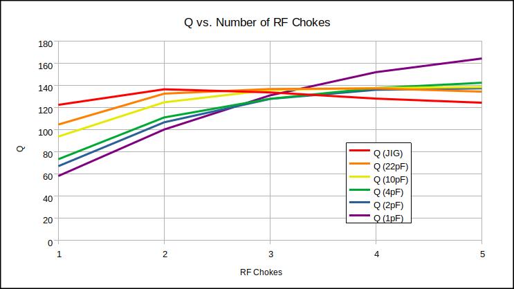
Above: A graph of the test data.
Observations:
- For this setup, LC Q = Vpp * 100.
- For < 1% reduction in Vpp, place the coil at a distance roughly the same as the form diameter.
- For 2% reduction in Vpp, place the coil at a distance of roughly 2/3 the form diameter.
- The relationship seems to follow the inverse square of the distance, which makes sense.
I need to see if cutting a hole in the plate makes any difference, and also test a slit from plate edge to hole to "unshort" the plate "winding". My feeling is that these efforts won't influence things much.