Let's Design and Build a (mostly) Digital Theremin!

Posted: 2/28/2025 2:01:06 AM
dewster

From: Northern NJ, USA

Joined: 2/17/2012

20mH Solenoid

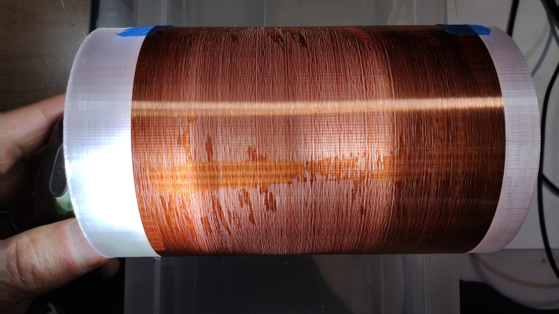
I 3D printed a clear PETG coil form, diameter 88mm and 140mm long, with 2 separately printed rib stiffeners added to the inside:

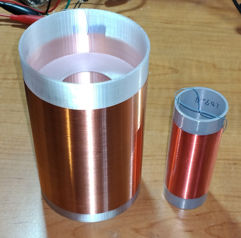
The print Z-stepping was set to 0.18mm, which is the OD of 34AWG single coat magnet wire.  Even with these as a guide, winding it was something of a bear.  The final inductance was somewhat off of that predicted by my coil program at 19.3mH.  DCR was 148 ohms.  Aspect ratio is 1.5.

On the test jig resonance was 1.66Vpp @ 265kHz, which means a Q of around 155.  Not super hot as the kit inductor Q's are around 170, but not super bad either.

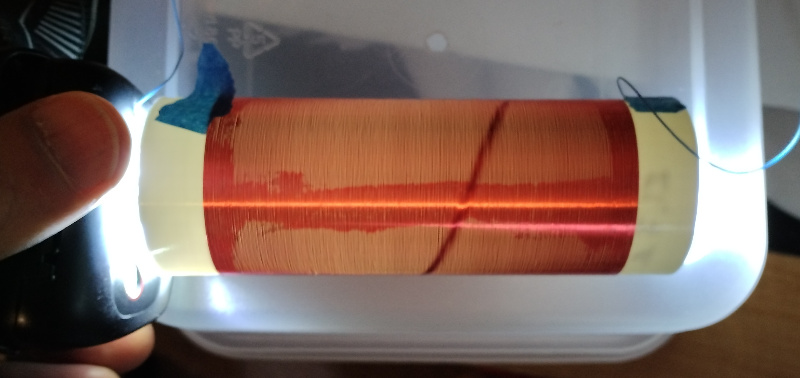
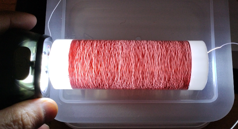
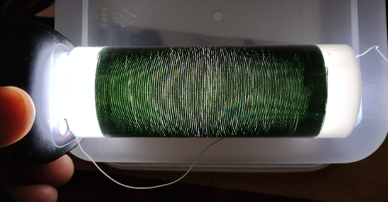
Also messed with a bit of ferrite in a smaller 1mH solenoid:

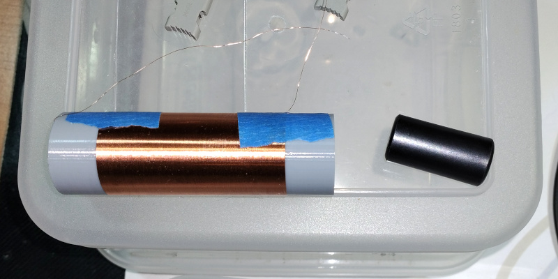
Resonance before and after inserting the ferrite was 1.1723kHz => 765.2kHz, or a 2.35 magnification of inductance.  Q before and after was 131 => 114.  Again not the best but not crazy bad.  

I need stick both of these in the freezer to see what's going on with their tempco's.  My new LCR meter has more resolution than my old LC meter, and I guess I trust it more to be stable over the warm-up period.

Posted: 2/28/2025 5:53:43 AM
ILYA

From: Theremin Motherland

Joined: 11/13/2005

Yo, fam, them homemade coils you got lookin’ like our chicks from the model spot, yo! They rockin’ that 90-60-90 vibe too, huh!

Posted: 2/28/2025 2:26:37 PM
dewster

From: Northern NJ, USA

Joined: 2/17/2012

"Yo, fam, them homemade coils you got lookin’ like our chicks from the model spot, yo!"  - ILYA

Thanks homey, they do look pretty.  My favorite is TechFixx green wire on PVC.  The Remington wire I'm forced to buy (TechFixx only offers double coat now) has little kinks through the entire spool, and gets worse near the end.  I imagine this contributes to the winding difficulties.

"They rockin’ that 90-60-90 vibe too, huh!"

It took me a bit to figure out this was 36-24-36 in metric! :-)

Posted: 3/1/2025 1:43:39 PM
dewster

From: Northern NJ, USA

Joined: 2/17/2012

Kinky Business

Here's a more revealing and uglier view of my latest 9.3mH coil:

I'm holding a flashlight inside the coil which shows the irregularity of the windings.  The upper bright horizontal stripe is room lighting, the lower ragged darker stripe is a line of clear nail polish, and isn't normally apparent.  Remington wire is kinda lame.

Posted: 3/2/2025 10:00:49 AM
Mr_Dham

From: Occitanie

Joined: 3/4/2012

If the tube is a stack of circles and the coil is a spiral, the wire has to come out of its track on each turn, right ?
This may also have an adverse effect, no ?

Posted: 3/2/2025 12:23:48 PM
dewster

From: Northern NJ, USA

Joined: 2/17/2012

"If the tube is a stack of circles and the coil is a spiral, the wire has to come out of its track on each turn, right ?"  - Mr_Dham

Very true.

"This may also have an adverse effect, no ?"

Before attempting any winding, I imagined the same thing, that I would need to do a "vase" type spiral print.  But simply stacking the ridges does help to corral the windings.  It certainly makes the first few windings at the start quite a bit easier.

Here's an image of a gray PETG coil, where the dark spiral is an indication of overcrowding (i.e. the print layers are just shy of being big enough) - the windings are quite tight:

And here is a coil wound on smooth plastic plumbing, where the kinks are super obvious and the unintentional spacing lowers the final inductance:

Here's Tech Fixx wire on smooth plastic plumbing, not nearly as kinky:

You must be logged in to post a reply. Please log in or register for a new account.