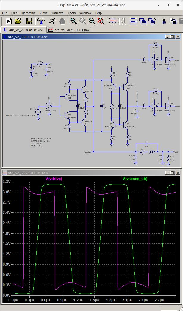
[dewster] The main thing that scares me at this point is the delay introduced by the current mirror and C4, which might be rather temperature dependent? I'm not sure emitter degeneration resistors R3 & R4 are necessary, but I worry about thermal runaway here.
Definitely, there should be big enough latency introduced by current mirror running in this mode.
Current mirror may give you almost zero (<1ns) latency when integrated voltage does not exceed the limits switching them to into saturation.
Just increase C4 to keep integrator output within 0.5V from power rails. One more thing missing in your current sensor is a biasing for C4.
Now it's biased due to the limits by rails. Once amplitude go beyond the limits, sense signal will turn into sine touching positive or negative rail, with distortion close the rail.
Putting high nominal resistors to bias around VCC/2 (e.g. 47K or 100K) should give better result, pure sine wave centered close to VCC/2.
Another concern can be simplification of current mirrors - 2-BJT mirror will give bigger output range but probably bigger delay or less linearity (not sure).
But it will make it harder to convert to square wave. Fast comparator (e.g. adcmp600) might do such conversion (see v2, v3, v4 versions of AFE on github).
Another issue with this type of current sensing (integration) that with the same current, lower frequency you will get higher voltage swing on output, and higher frequency will give lower swing.
Using of comparator and choosing proper C4 value keep the current sensing sine output below bounds in frequency and current range could help.
I'm not sure about R3 and R4, but I have concern regarding R1, R2. Doesn't it makes sense to replace them with current sources? (+4 BJTs)
Is your goal to design BJT + invertor only AFE?


