I have started this thread as a place where:
A:) Questions / Answers / Advice etc can be exchanged regarding obtaining real-world data from actual theremins designed or REALLY based on designs by Lev Termen (RCA, Claramin etc, and tube clones of these)
B:) Where results, or links to results / images / recordings etc can be placed.
Other than discussion relevant to obtaining the above, I would prefer it if this thread was not used for technical analysis of any results obtained - The exception to this perhaps being advice / requests for data which is "missing" and arguments for obtaining such data.
I will start by moving a posting replying to Hobbs who is hoping to do some probing.. ;-)
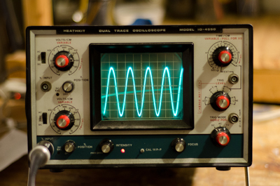
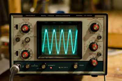
" Send me the marked up schematic w/ the test points ( or even a verbal list- ie: grid of v3 ;or junction of T6 and r15) and Ill get started on "catching some waves" for you. "
Here we go ;-)
Refer to Art Harrisons drawing Pg 2, Rev 11, 3-04-04 :
V2 = 224 Tetrode mixer, V1 = 227 Triode Pitch Oscillator, V3 = 227 Triode Ref oscillator, V4 = 227 triode Audio preamplifier, V7 = 171A Triode Audio power amplifier
Plate of V2 in as much detail as possible. The mixer waveshape should be visible here, even if as an 'envelope' containing HF.*
GC (cap) of V2 = Waveform from Reference Oscillator - Ideally noting amplitude and any DC offsets.
SG of V2 = Waveform from Variable Oscillator - Ideally noting amplitude and any DC offsets.
Grid of V4 = Input to pre-amp.
Plate of V4 = Output from Preamp*
Grid of V7 = Audio output / Speaker connector.
Then a high quality (miked) audio recording from the speaker covering full frequency and volume ranges would be the icing on the cake! ;-)
*These points may not give representitive voltage waveforms, as they are current sinking from a low-R high-L load - But nonetheless checking the voltage waveforms should give useful data.
Fred.


