Antannae non-linear relationship

Posted: 10/25/2012 12:17:33 AM
FredM

From: Eastleigh, Hampshire, U.K. ................................... Fred Mundell. ................................... Electronics Engineer. (Primarily Analogue) .. CV Synths 1974-1980 .. Theremin developer 2007 to present .. soon to be Developing / Trading as WaveCrafter.com . ...................................

Joined: 12/7/2007

"I believe this only applies to designs that have linearizing coils that are quite a bit larger (i.e. quite a bit more inductance) than the tank coil" - Dewster

Bingo! - And the only effective linearizing coils (at least in "normal" theremin designs) are ones which are much larger than the tank coil/s - it is the increased inductance of the linearizing coils which enables "amplification" of the sensitivity to the tiny changes in antenna capacitance - this "amplification" is compensated (partly counteracted) by having much smaller tank inductance and much larger tank capacitance..

The smaller tank inductance with large tank capacitance makes the oscillator quite insensitive to capacitance changes, but quite sensitive to inductance changes.. This sensitivity to inductance changes allows the "virtual" inductance applied due to the changing resonant frequency of the antenna resonant circuit, to have a major effect on the oscillator frequency.

As this "virtual" inductance change has a different law to the law governing the antenna capacitance change, when "right", one gets a linearized response.

So my little speach above applies to conventional theremin equalizing - and I think applies to Lev's theremin designs, albeit I suspect the Lev oscillator obtains a somewhat different interaction due to its topology (my untested hypothesis)..

But the above is not the only way to obtain linearization - For me, the real irony of all this is that I spent years playing with a "different way" - and achieved it - an analogue circuit monitors the VFO frequency, converts this frequency to a voltage, and a processed version of this is fed to control the equalizing inductance using saturable reactance ...

I know you have been playing with a different topology as well -

To me, the profound irony is that, IF we have discovered the Lev linearity secret, we may well have discovered it a few decades too late to make best use of it - Our technology and understanding may have now caught up with where Lev was in the early 30's !  -- And we may well be able to achieve better linearity than he did, using our present technology.

Oh - I may be completely wrong about Lev's oscillator - I would be dissapointed if I was wrong, because that would mean that the expierience of "getting inside Lev's head" would have been an illusion.. And "cracking" this "mystery" has been something of a high point for me.. But if it turns out to be "just another oscillator" well, I can live with that! ;-)

But I dont think it is! ;-) .. The Armstrong oscillator was perfectly capable of operating with tubes (it was designed for tubes) and Lev could have implemented the equivalent of our parallel LC theremins using the conventional Armstrong oscillator more simply than the oscillator he designed -

I think Lev deliberately split the inductances and implemented series LC configuration because this conferred great advantage for his theremin application.

Fred.

Posted: 10/25/2012 12:41:10 AM
FredM

From: Eastleigh, Hampshire, U.K. ................................... Fred Mundell. ................................... Electronics Engineer. (Primarily Analogue) .. CV Synths 1974-1980 .. Theremin developer 2007 to present .. soon to be Developing / Trading as WaveCrafter.com . ...................................

Joined: 12/7/2007

"This is a major design decision IMO because it very much impacts the effort and expertise needed for factory and subsequent field calibrations of the pitch section" - Dewster

This problem is entirely overcome if one tunes the antenna resonator only, and never touches the reference or variable oscillators after they have been "factory" calibrated..

And "factory" calibration is a lot easier - You have a known reference oscillator frequency (or will have due to design and results from pre-production prototypes) - You have an expected "mean" antenna capacitance, and one can simply set these using reference parts, and adjust the variable oscillator with the antenna resonance control set to 'mid'..

Therafter, the user tunes the antenna resonance - the effect will be the same as conventional tuning control, except that linearity will be constant regardless of the environment.

Posted: 12/15/2012 4:47:55 PM
dewster

From: Northern NJ, USA

Joined: 2/17/2012

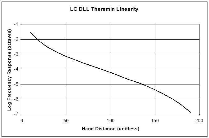
Today I'm playing around with DLLs (delay locked loops) rather than DPLLs as a source for tank excitation.  Was wondering how the theoretical linearity qualitatively compared to RC and LC oscillators, since it is the period (the inverse of frequency) that would be used as the operating point.  Did the previous Excel exercise for LC period:

Resonant period of an LC tank = 2*pi*((L*C)^(1/2))

Which is a C^(1/2) relationship.

Antenna & hand capacitance are 1/ln(x).

Together these give a [1/ln(x)]^(1/2) relationship.

Heterodyning this gives:

[1/ln(x)]^(1/2) - Flocal   (note: subtraction is reversed because delay increases with capacitance).

I need to put this in my full sim and see if it is any easier to linearize than the LC oscillator case.  The mid and far fields seem a bit more linear, near field is somewhat less linear.

Updated spreadsheet is here:

http://www.mediafire.com/?5jjmyescggks5yj

Posted: 12/15/2012 10:32:23 PM
FredM

From: Eastleigh, Hampshire, U.K. ................................... Fred Mundell. ................................... Electronics Engineer. (Primarily Analogue) .. CV Synths 1974-1980 .. Theremin developer 2007 to present .. soon to be Developing / Trading as WaveCrafter.com . ...................................

Joined: 12/7/2007

Funny - we seem to be doing many similar things at the same time! ;-) .. When I get my teleporter working we could probably have the perfect theremin up and running in weeks!

One "problem" I have with your spreadsheet is the "unitless" nature of the output - Probably something I could sort out if I wasnt an idiot, LOL ;-).. The actual usable playing field is (IMO) critically dependent on the real distances related to the linearity curve - and in this respect topologies vary greatly -

Below is a simulation of a 555 based (RC) theremin - I have been playing with schemes to linearize this using reactive components in the feedback path (started with just a capacitor, but now looking at a tuned RLC)

- the simulation below is just a simple RC.

I have placed octave markers (blue spikes) so that the linearity (or lack thereof) can be quickly seen.

One notable thing about the simple RC oscillator is that no matter what one does, it seems one is limited to about 45cm from the antenna as the maximum playable distance, and if one wants to keep the response 'natural' (as in, distance between octaves stretch as one goes more bass) then the playing range is about 40cm max.


 The original images etc can be found at E-14 Theremin Group

 Fred.

Posted: 12/16/2012 3:52:52 PM
dewster

From: Northern NJ, USA

Joined: 2/17/2012


"One "problem" I have with your spreadsheet is the "unitless" nature of the output - Probably something I could sort out if I wasnt an idiot, LOL ;-).. The actual usable playing field is (IMO) critically dependent on the real distances related to the linearity curve - and in this respect topologies vary greatly"  - FredM

Agreed, the quickie linearity spreadsheet is just a qualitative thing.  It's interesting that linearity looks largely the same (though it may have different ranges in practice) regardless of what kind of excitation or measurement is used.  Even the inverse of the frequency looks much the same as frequency when both get heterodyned down to nearly zero.  The big caveat here is EQ, but I wouldn't be surprised if every well designed and constructed Theremin in existence couldn't be tuned to have a fairly linear middle pitch field, with tone cramping in the near and far field (with the far field cramping relaxed somewhat by the hand approaching the body).

"One notable thing about the simple RC oscillator is that no matter what one does, it seems one is limited to about 45cm from the antenna as the maximum playable distance, and if one wants to keep the response 'natural' (as in, distance between octaves stretch as one goes more bass) then the playing range is about 40cm max."  - FredM

Nice graphics!  I gotta say, playing 1/2 a meter from the antenna isn't too shabby. 

If the Theremin didn't already exist I wouldn't believe that it could exist, that sensing tiny changes in the tiny capacitance of the hand a significant distance away from a small antenna could be stable enough and noise free enough to play serious music.  Which I suppose is what keeps me fascinated with it.  That, and it's a wonderful playground on which to hone almost everything one knows about electronics.

Posted: 12/16/2012 10:14:05 PM
FredM

From: Eastleigh, Hampshire, U.K. ................................... Fred Mundell. ................................... Electronics Engineer. (Primarily Analogue) .. CV Synths 1974-1980 .. Theremin developer 2007 to present .. soon to be Developing / Trading as WaveCrafter.com . ...................................

Joined: 12/7/2007

" it's a wonderful playground on which to hone almost everything one knows about electronics." - Dewster

It most certainly is that!

I have never undertaken anything which has educated me more - Back in the 80's I took on a design to control the deposition of a one molicule layer of phospholipids onto a substrate - it had to maintain precisely one layer of lipids on the surface of a trough while the substrate was dipped... I never imagined that I would find something as "simple" as a theremin could pose any challenge after having achieved that! - But that job took less than a year - and here I am after having spent at least 5x as long on theremin R+D.

But I have learned more about electronics in this time than over the entire 30+ years preceding it.

Fred.

Posted: 12/17/2012 2:11:01 AM
FredM

From: Eastleigh, Hampshire, U.K. ................................... Fred Mundell. ................................... Electronics Engineer. (Primarily Analogue) .. CV Synths 1974-1980 .. Theremin developer 2007 to present .. soon to be Developing / Trading as WaveCrafter.com . ...................................

Joined: 12/7/2007

"(with the far field cramping relaxed somewhat by the hand approaching the body)." - Dewster

I am not sure that this is true..

Evaluating the true capacitance distribution is beyond my mathematical ability - but as I see it, the "simple" evaluation (which I use) has one possibly major error component:

This method is based on a "background" capacitance - the capacitance "seen" by the antenna to all unmoving grounded objects - these "objects" as I see it, include the stationary body of the player.

Then there is the hand <-> antenna capacitance, which is calculated as a grounded "plate" of fixed area, moving with respect to the antenna. This "plate" is coupled to ground galvanically via the body, and therefore its proximity to the body, as I see it, will not change its coupling to ground (or at least not to any noticable extent).

As this plate (hand) moves towards the body, its (capacitive) significance will be purely determined by proximity to the antenna, not by its proximity to the body - if the hand was to merge with the body, one would be left with the "background" capacitance as the only capacitance seen by the antenna.

The primary "error" component:

The simple analysis above ignores a significant source of changing capacitance - the arm. Fully extended (close to the antenna) there will be increased capacitive coupling of the body to ground (via the arm), and there will be increased (depending on the antenna length) angular coupling of the antenna to the arm - One cannot view the hand as an isolated grounded plate with the arm as an insulated means of moving this (which is what the simple analysis does).

The change in the arms capacitive coupling to the antenna is, I think, less severe than the capacitance change contributed by the hand (as in, the delta or change will not be inverse square of distance I think - it will be this modified by some function based on angular proximities of the antenna to the arm) - I think (and my experiments with longer and thinner antennas than usual leads me to think my hypothesis may be valid) that the arm actually improves linearity over about 50% of the playing field nearest the antenna.

But as the arm approaches the body, I think that its angular capacitive coupling to the antenna drops sharply, and possibly makes bass compression more severe (comparatively).

However, as you will appreciate, making measurements which are conclusive, or actually measuring real capacitances in order to determine causitive mechanisms is not easy ;-) .. So all the above is little more than unsubstantiated hypotheses.

I am sure that with mathematics (I think primarily integration to determine the angular capacitive components of the antenna to the arm - increase in coupling of the arm to ground should be a simple linear function of area) it would be possible to plot the arms significance, and the effect of antenna length on linearity..

But I will leave that till after I have a maths co-processor implanted! ;-)

Fred.

Posted: 12/17/2012 10:11:26 AM
FredM

From: Eastleigh, Hampshire, U.K. ................................... Fred Mundell. ................................... Electronics Engineer. (Primarily Analogue) .. CV Synths 1974-1980 .. Theremin developer 2007 to present .. soon to be Developing / Trading as WaveCrafter.com . ...................................

Joined: 12/7/2007

"Nice graphics!  I gotta say, playing 1/2 a meter from the antenna isn't too shabby. " - Dewster

Thanks ;-) .. But that lowest octave (to 50cm) is completely unplayable - you really only get a maximum of 3 playable octaves from about 12cm to 40cm with this topology, and the simple TS555 RC setup as shown is a pig - with 12V supply one only gets a nasty 4V triangle wave on the antenna - one needs to buffer the 555 output and amplify it to a higher voltage, then mess with the input side so one gets a 10V signal on the antenna, before one gets anything remotely approaching stability and noise immunity - just not worth the effort unless one also redesigns the feedback mechanism to improve the linearity.

I say the above just to warn anyone thinking I am "endorsing" the design in any way - I simply did this analysis for educational purposes (and as part of a book I am compiling - a theremin designers guide - which may one day get published)

Fred.

Posted: 12/30/2012 6:37:05 PM
dewster

From: Northern NJ, USA

Joined: 2/17/2012

"The simple analysis above ignores a significant source of changing capacitance - the arm"  - FredM

Exceedingly good point.  For some reason I wasn't even thinking of the arm.  I agree that it could be modeled (along with the hand and body) with much more fidelity to reality - but the person to do that probably won't be me either!

You must be logged in to post a reply. Please log in or register for a new account.