This thread has been started because: (This stuff is purely hypothetical at this stage !)
a.) In discussion over on the Theremini thread, I made an OT posting about my capacitive ribbon instrument.
b.) Peter then said it seemed to have some similarity to the Continuum fingerbaord, and gave some details about this instrument.
c.) Dewster and I then investigated the Continuum and started to discuss possible technology by which to implement an alternative embodiment of something similar -
If discussion on this continued at the Theremini thread, this would represent a hijack of that thread, and would also be another subject likely to get lost as its not related at all to the theremini.
As to whether this thread will develop into anything, who knows... ;-)
=============================
Coalports original description of the Continuum:
The continuum interface is a neoprene pad that has a satiny-smooth woven upper surface applied to a thin rubber sheet (same stuff as a mouse pad). It is sensitive to the slightest motion of the hand. The "keyboard" that you see printed on the fabric is strictly a visual aid for placement of the finger (or fingers) and if you want to hit a note precisely, you must be in the exact center of the printed "key". If you are off by the slightest bit, you will be flat or sharp (similar to the theremin). Yes, you can quantize your sound if you want to, but I do not.
When I want to play the pad like a keyboard, I hit the notes precisely and then apply pressure for volume. If I want to "gliss" like a theremin, I apply pressure and then slide to where I want to go. There is no "toggling" as there is on an ondes - I was landing on precisely the right points to get the correct pitches.
Underneath the neoprene pad there is a mind-boggling row of thin metal bars that "float" on hundreds of delicate springs made of steel as fine as hair. Woe betide those who attempt to look underneath the neoprene without knowing exactly what they're doing. I had my own baptism of fire, thank you very much!
On the other hand, I now know how the damn thing works.
==============================================
FredM's Reply to Dewsters comment:
"That thing's crying out for capacitive sensing via FPGA." - Dewster
Having now seen pictures and explanations etc of how the Continuum fingerboard is constructed and operates, I agree with you Dewster -
This instrument is just crying out for simplification, and this simplification could probably be achieved with capacitive sensing and FPGA better than by any other means.
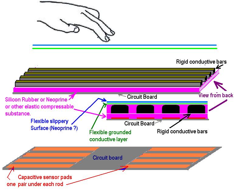
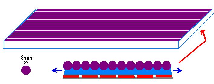
The the magnetic fields from the fine magnetic rods in the fingerboard are sensed by hall devices at each end of each rod, so that finger pressure and placement can be determined and processed - if these rods were non-magnetic, grounded, and capacitive sensing pads placed beneath them, exactly the same data could be derived with even higher resolution than the hall sensors are capable of.
The mechanics could be hugely simplified, the grounded rods would be between the player and the sensors, so there woulf be no capacitive interference problems, and my guess is that the whole fingerboard could be produced at a fraction of its current price.
All the existing algorythms and firmware (which is the clever bit of the Continuum IMO) should work with a capacitive fingerboard, and the 2 hall sensors required for each rod replaced with simple copper sensors (probably just PCB tracks).
======================================
Dewsters reply to above:
"The mechanics could be hugely simplified, the grounded rods would be between the player and the sensors, so there woulf be no capacitive interference problems, and my guess is that the whole fingerboard could be produced at a fraction of its current price." - FredM
I'd try to leverage the huge I/O count in even a low-end FPGA to simplify the hardware even further. From top to bottom:
1. The top neoprene mouse pad stuff.
2. A flexible ground layer.
3. A flexible insulating layer.
4. A flexible layer of short narrow conductive parallel strips, maybe 5mm wide spaced 5mm apart, running front to back.
5. A springy insulating layer of some sort (more neoprene?).
6. A layer of long, narrow conductive parallel strips with the same dimensions as layer 4, but running from left to right.
This forms a huge XY capacitive grid. Sequentially drive the layer 6 strips, and watch the response on the layer 4 strips using RC time constants.
With this setup you could track loads of fingers on the thing. You could probably DIY it for almost nothing (<= big talk).
============================================
REFERENCE STUFF:
Continuum mechanics:

Details of the operation can be found here.
============================================
Ok - Ready to go ;-)
Fred


