Ethervox MIDI Theremin

Posted: 5/18/2014 9:09:55 PM
synox89

Joined: 11/16/2013

Hello, com,


I am working on a presentation for my exams in high school. I've chosen to talk about the theremin and its capabilities to resemble a violin. For this purpose I would like to know what possibilities are there to imitate this instrument? As far as I have found out, there is a possibility to convert the signals of the theremin (the voltage) to MIDI commands. An example for that would be the Ethervox MIDI Theremin (link: http://www.theremin.info/-/viewpub/tid/16/pid/5). I couldnt find any information on how the conversion is done.


There are also these CV-to-MIDI-convertors (link: http://www.schneidersladen.de/en/doepfer-a-192-2-cv-to-midi-usb.html). Are they implemented into the Theremin mentioned above?


Unfortunately I barely can find anything about the functionality of these. Could anyone guide me a little?


Thank you,


sincerely,


Alex

Posted: 5/18/2014 9:57:45 PM
FredM

From: Eastleigh, Hampshire, U.K. ................................... Fred Mundell. ................................... Electronics Engineer. (Primarily Analogue) .. CV Synths 1974-1980 .. Theremin developer 2007 to present .. soon to be Developing / Trading as WaveCrafter.com . ...................................

Joined: 12/7/2007

OT  - Note for other forum users:

This thread is NOT about the Moog Ether-Vox!


Hello Alex,

You perhaps picked one of the worst instruments (Ethervox MIDI Theremin) to get information on - Only a few of these beautiful instruments were built, little technical data is available, and seeking out more data is probably a task that will consume all your project time but still leave you empty handed.

In terms of the general question "I've chosen to talk about the theremin and its capabilities to resemble a violin." I think any focus on MIDI is probably a bad idea - The theremin is naturally well suited to approximating a violin type sound, primarily due to the way it is played .. Like the violin it can play any audio frequency (is not tied to any fixed scale) and this allows the player full control of modulations glissando's vibrato, portamento etc - The thereminist also has full control  of dynamics, so theoretically anyway, can "emulate" bowing.

The sound from some theremins can be quite cello or violin like - I think this is particularly true about theremins designed / built by the inventor, and some other vintage and tube theremins, but it is even possible to approach a cello sound on some modern instruments.

If one needs an external "sound engine" to create violin / cello sounds, IMO voltage control is the better route - MIDI does not (IMO) have the required speed and resolution to do the theremin justice (or, more importantly, most [if not all] available MIDI synthesizers do not have the ability to process the continuous data required from a theremin - as in, they take MIDI Note-ON/OFF but not CC to control pitch and dynamics - to capture theremin control the theremin would need to continuously transmit high resolution MIDI for pitch and volume, and the synthesizer would need to produce the sound based on this data

An Etherwave + (which has voltage outputs for pitch and volume) can drive a basic analogue synth on which a reasonable violin / cello sound can be engineered - A couple of ramp waveforms at the same frequency with slight phasing followed by a VCF and VCA can give a nice string sound.. Even a single ramp->VCF->VCA is passable.

Regardless of how good (or bad) the sound engine is (whether the theremin itself or a synth) a passable violin or cello sound will only happen from the hands of a skilled player - because (IMO) at least 50% of the "emulation" comes from the way pitch is changed and modulated, and how the dynamics are 'moved' - Yes, one needs a sound that underpins the playing (you need a sound at least with a reasonable spread of odd and even harmonics approximately in right 'places' at the right levels - You will never get a convincing violin from pure sine or signal containing only odd harmonics) - but control is IMO more important than the sound.

MIDI does allow "canned" strings to be played - hell, you can "play" a violin on a keyboard - but this is achieved through envelope shaping - with a theremin, using MIDI, you are letting the "engine" take away the one thing that makes the theremin special - the control - and passing this control to "the machine".. If you use a theremin to produce MIDI Note data, and use this to drive a MIDI "violin" synthesizer, you may as well use a keyboard - you get no advantage from the theremin, and a LOT of disadvantages!

Good luck with your project! ;-) ... And feel free to ignore the above "advice" - I am just a grumpy old man!

;-)

Fred.

"As far as I have found out, there is a possibility to convert the signals of the theremin (the voltage) to MIDI commands"

Oh, one important thing I failed to mention - Most theremins don't have any 'voltage' or digital signals controlling the pitch - the pitch is generated by heterodyning two HF oscillators - but I am sure you know this! - When pitch voltage is obtained, it is (usually - some notable exceptions from Moog) from a separate frequency (or period) to voltage converter.. But most theremins dont have these fitted.  Digital outputs are derived either from A/D of such a generated voltage, or from directly 'counting' the period of some derived frequency - but that subject is probably way beyond the level you require ;-) .. The only "control voltage" found in theremins is generally  for the volume circuit (VCA).

All you need to know about  the technical side of common theremin topology can be found here..

http://www.suonoelettronico.com/downloads/HotRodEtherwav.pdf

If you read nothing else, read up to (and including) "tone production and pitch control" on page 3.

These two articles from the excellent synthesis series in "Sound On Sound" explain the fundamentals of synthesizing bowed instruments:

http://www.soundonsound.com/sos/apr03/articles/synthsecrets48.asp

http://www.soundonsound.com/sos/May03/articles/synthsecrets49.asp


Posted: 5/19/2014 7:53:29 AM
synox89

Joined: 11/16/2013

Hello, Fred!

Thank You very much for your quick response! Well, as far as I am, I actually plan to make some sort of a theremin model, which should produce some wave. I just want it to make some controllable noise. Maybe if You are interested, you could take a look at the plan, I am working currently on it.


To return to the topic, as far as I got it now, a MIDI solution is most likely predetermined to have some latency problems. But what about the Ethervox Theremin? Would it be safe in my presentation to approach both solutions - the MIDI and the "filtering" one, saying that the MIDI is rather a solution by circumventing the actual question: "Can a theremin resemble/replace a violin?", because the native sound is not only altered but completely omitted?

And sorry for my numerous questions, my English is my second language. :-)


How does the signal (let's say a sinus wave) get converted into another dynamic wave? The violin overtones alter throughout a short sample. In the beginning we have a plethora of overtones, which at the end, fade out and the main tone remains.

How is this sort of thing applicable?


sincerely,


Alex

Posted: 5/19/2014 9:03:46 AM
FredM

From: Eastleigh, Hampshire, U.K. ................................... Fred Mundell. ................................... Electronics Engineer. (Primarily Analogue) .. CV Synths 1974-1980 .. Theremin developer 2007 to present .. soon to be Developing / Trading as WaveCrafter.com . ...................................

Joined: 12/7/2007

Hello Alex,

Have a look at posting #11 Here:

http://www.element14.com/community/thread/10541/l/electronics-for-theremins-1

This is a mixer which produces a ramp waveform (and also triangle and square)..

This mixer needs logic level inputs you can get from a comparator input.. But at this time I am reluctant to swamp you with too much technical data.. I see you are running LT-Spice which is a good sign! - but if you want to build even a simple theremin capable of approximating a violin, there's quite a lot of work and understanding required!

Basics you need:

1.) Front end for pitch - that's oscillators and mixer.. I would use my mixer for ramp waveform, so between oscillators and mixer you (most likely) will need a circuit to convert oscillator output levels and waveforms to logic levels (I use LM393 comparators for this).

2.) Some form of low pass filter for the ramp - at simplest, this is a simple RC filter - but to really get closer you need a VCF.. Which opens a big can of worms because you then need some form of pitch->voltage converter to drive it..

3.) Volume antenna and volume circuit, and VCA.

I think you will only (unless you have LOADS of time and are really good at electronics) going to stand a chance if you cobble together 'sections' from tried and tested designs - The EPE-2008 is a good basic theremin that could be adapted IMO (I would advise the Jaycar / SC basic kit, but sadly this does not use an independent VCA, so isnt ideal for what you need to do - although it could be adapted) .. I would be willing to email a copy of this to you.. And could advise on adapting the design, but if you needed a lot of help I would ask you to make a small donation to http://www.healkids.org/ - I can either spend my time fundraising for them or helping theremin builders, so I try combine these! ;-)

<--- My email is my avatar

Fred.


Posted: 5/19/2014 10:02:49 AM
synox89

Joined: 11/16/2013

Hi Fred!


No, I cant realize this project yet. I have actually only 4 days left. The model of the theremin is actually rather a good gimmick than a real contribution to the solution of the question. Just to make a good impression, you know. :-) A realization would be waay beyond the demands of my teacher. (its "just" a high school final exam)

I just want a circuit which reacts to a hand approaching its pitch antenna. It doesnt even have to be so precise in the wave form and there is no need for a volume control. I only want to make this circuit I posted work. I actually built it but it doesnt make a sound and I think I should check the inductors...

The real essence of my presentation will be just how this could be theoretically achieved. The problem is that I have only 20 Minutes for it and by being honest, I am not good in electronics either. :S

I stopped the time and so far I need too much time even for a short introduction of the theremin and the violin in terms of the functionality of the theremin and the musical capabilities of them both. After this I want to explain how their timbre differentiates from one another. There I will have to make a short trip into acoustics, where I explain what Fourier analysis goes.

So there wouldn't be so much time left for the solution (maybe 7-8 Minutes) of the question, which is the main part of this kind of presentations.

And yes, You are right. I have many difficulties with dealing with the technical data..  From where can I start? Lets say, I have a sine wave from a Theremin. What do I need? As far as I found out, the overtones of a Violin alter in their volume over time. So:

1. How can be added overtones to a sine wave, which also

2. Change to a certain pattern (fading out solely of the overtones at the end).

I would be very glad if you could guide me in this direction. If it turns out well, I will love to help you with your great activity. :)

I wouldn't mind if you right to me per email as well: salzstangenmann@googlemail.com

Sincerely,


Alex

Posted: 5/19/2014 1:29:11 PM
FredM

From: Eastleigh, Hampshire, U.K. ................................... Fred Mundell. ................................... Electronics Engineer. (Primarily Analogue) .. CV Synths 1974-1980 .. Theremin developer 2007 to present .. soon to be Developing / Trading as WaveCrafter.com . ...................................

Joined: 12/7/2007

Hi Alex,

Ok - your schematic / simulation..

Most interesting! (and an utter nightmare ;-) - where did you find it? did you wind your own inductors? ... I believe you could be in trouble with this one, lets go over how it works in simulation, but not in reality:

There is a fixed frequency oscillator 'round Q1 - frequency of oscillation determined by L1,C1 .. L2 is the "tickler" coil to provide feedback, L3 is effectively the coupled oscillator output coupling the HF to the mixer 'round Q3.

Same applies to the variable oscillator 'round Q2 - L6 and C2 set the frequency, and antenna capacitance is added to C2, L4 is the "tickler", and L3 couples the variable HF to the mixer.

Now, in simulation, all components are ideal - so if you removed C3 both oscillators would run at exactly the same frequency, and adding C3 lowers the variable oscillator a bit more than 1kHz, so when the oscillators are mixed you get ~1.5kHz.

But in reality you could have as much as 10% variation in capacitor / inductor values (which determine the frequencies)

You need some way to tune this beast!

On the link I gave for my mixer, an earlier post shows an adjustable length antenna - this could help you tune it... But you will probably (almost certainly) need to trim either  C1or C2 (add small capacitance) or put a trimmer there..

1. How can be added overtones to a sine wave, which also

2. Change to a certain pattern (fading out solely of the overtones at the end).

There is no "end" with the theremin you are building - it is always on - the only way to silense it is when both oscillators are at the same frequency, and to set this "null" point (by tuning) so its at its limit (pitch doesnt start to rise as you go away)

Dont even think about dynamic overtones (or even overtones) at this stage - if you have 3 days, you will be lucky to get anything even remotely playable! - anyway, from the simulation you are not getting sine - there are a few overtones there ;-) - probably even more in reality... (I suspect if you reduce C3 and therebye the audio frequency, there will be more overtones..)

The "nightmare" is the coils - 3 windings on a common core (I hope you have used a common core for [L1.L2 and L3] and for [L4,L5 and L6] - no chance of it working otherwise) is a tricky thing to get right unless you have an accurate inductance meter or bridge - particularly the 5uH  -  I am actually surprised this works even in simulation - I would have worried about 5uH being enough to couple sufficiently to Q3 .. Could you email me the simulation files?

Fred.

Posted: 5/19/2014 2:28:17 PM
synox89

Joined: 11/16/2013

Hi, Fred!

I've got this plan from another board where I simultaneously ask for help. A very helpful user made the effort to draft it.


And no, I didn't wind up my own inductors. I just bought all components according to the plan. And so I ended up with two different types of inductors:

The first one is the 0,1 mH one, the one on the right 5 µH. I also had encountered the problem how to bring the inductors together. I put them as in the plan next to each other. (L1 L2 L3 and on the right L4 L5 L6) But there is for sure a problem about the angle i put them i suppose... It looks this way at the moment. It probably looks very sad i know xD:


I got the advice to get some magnetic coil to enhance the inductance of the 0,1 mH inductors. Can I just wind some additional coil on the inductor?

What I want to clarify is that I dont think about making this thingy produce some overtones and dynamic overtones. No no no, i just want it to make some noises which are alterable by the distance of my hand. This is more than enough. :)


But for the presentation I have to make some (it doesn't have to be so detailed) suggestions how these dynamic overtones could be added. Just some approaches.  What is needed (Highpass-, lowpass filters and so on)


I've sent you the project.


Sincerely,


Alex

Posted: 5/19/2014 3:43:57 PM
synox89

Joined: 11/16/2013

The links you've send me are very interesting (especially the SOS one), but there are many things I dont quite get..

As far as I understand a filter bank is splitting up a signal in its sinus waves and then it alters each separately. Eventually the waves get merged together.

In the second SOS Article (http://www.soundonsound.com/sos/May03/articles/synthsecrets49.asp) the author uses a bank to simulate

the resonance of the bridge:

http://media.soundonsound.com/sos/may03/images/fig01bowstringbridge.l.gif

But what does this picture exactly show?


And afterwards since the resonance of the body is very different by using the synthesizer from the bowing he says that he uses a lowpass-, highpassfilter and a resonance filter bank to model the violin timbre. I think that this is the very thing I am trying to do. But he doesnt quite explain it (maybe because of my knowledge), how he chooses the band filters. Do you have any idea?


sincerely,


Alex

Posted: 5/19/2014 9:45:06 PM
FredM

From: Eastleigh, Hampshire, U.K. ................................... Fred Mundell. ................................... Electronics Engineer. (Primarily Analogue) .. CV Synths 1974-1980 .. Theremin developer 2007 to present .. soon to be Developing / Trading as WaveCrafter.com . ...................................

Joined: 12/7/2007

Hello Alex,

Really sorry - but you may as well unplug the components from your board - you have NO chance of getting it to work :-( - to be honest, I wouldn't even attempt to build this without doing a lot of calculations and getting a specific coil former - but actually, wouldn't use this schematic anyway.. The only unusual thing about it which is interesting is the transformer coupling to the mixer circuit and the mixer itself.. You really need a circuit using pre-wound tunable transformers, like the Jaycar / Silicon chip kits, not something like this one! -

I am replying here as its educational and cautionary for others (perhaps).. Unfortunately, there are loads of " very helpful users" on the internet - but not as many who know what they are talking about, and those who do know often make assumptions about things that are obvious to them but not obvious to others.. (and I include myself in this group) - I jumped to the conclusion that because you had presented an LT-Spice schematic, you had "engineered" it yourself and understood more than you did! - using "K" indicate somewhat more knowledge than just the basics.

.. I strongly suspect the schematic you have  (LT-Spice)  has never been built.

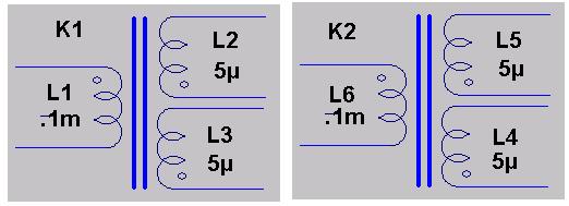
There are two critical lines of text in the schematic which change the way the circuit functions, these lines are:

(On left hand side): K1 L1 L2 L3 1

(On right hand side): K2 L4 L5 L6 1

What these lines do is define the inductors as coupled to form a transformer - So K1 is one transformer, K2 is another transformer - the statements group the windings, so for K1, its L1,L2,L3 in one transformer, and the coupling between these windings is 1 (no losses).. Also, you will see a dot on each of the inductors - this is the phase dot - and for L4 and L5 these dots are critical, it shows which end of each winding to connect!

You cannot use individual inductors - even if packed closely together - it simply wont work. This is what the circuit should be using:


"And afterwards since the resonance of the body is very different by using the synthesizer from the bowing he says that he uses a lowpass-, highpassfilter and a resonance filter bank to model the violin timbre. I think that this is the very thing I am trying to do. But he doesnt quite explain it (maybe because of my knowledge), how he chooses the band filters. Do you have any idea?"

Yes, I do have an idea of how its done (having made many string and bowed instrument simulations on analogue synths) but its a mix of art and science - Yeah, I know to start with ramps (or ideally ramps where the rising and falling slopes are independently voltage controllable) - then its as simple or as complex as you want - or can afford - Using bandpass filters you can selectively tune for individual harmonics, lowpass filters allow you to cut all harmonics above the cut-off frequency by 12 or 24db / octave (24db is a bit sharp and often unnatural sounding if using only one filter without boosting some of these harmonics with bandpass)...

Hmm.. I cant explain it - its really a hearing thing... This is the main reason I love analogue - you have knobs you can twiddle easily without having horrible digital menus to navigate - so you can do it by ear and not need mathcad running on your PC to tell you what numbers to enter! ;-)

So no, I cant explain it better or easier than the SOS articles, Sorry!

Fred.

Some back-of-envelope calculations:

Oscillator frequency =  ~ 734kHz

Sensitivity to tank inductor (0.1mH)  change = 4kHz / uH

Sensitivity to antenna capacitance change: 0.9kHz / pF

What the above means is that the inductors are critical (way too critical).. Then theres the 10's of pF randomly created by the plug-in breadboard (which itself is enough to make even a good circuit dysfunctional) .. Sorry!  But its a great way to learn! ;0)

 -> Got the file you sent, and I cant even get the circuit to run in simulation! - But im not going to spend any time on it...

Posted: 5/20/2014 6:31:32 AM
synox89

Joined: 11/16/2013

Hello, Fred!

So, you couldn't help me further with the circuit? (it's just I need to know how to proceed further with the presentation).


And basically I understand what bandpassfilters do. In fact, I have also a quite OK DAW (FL10) where I have done some experiments and could create some sort of a violin sound. :)

But what I want to know is, how the sound (lets say a sine wave), coming from a theremin, is filtered in real time. Can it make the theremin sound like the violin in real time?
 What devices are needed? Can you give me some key words to research on?


Sincerely,

Alex

You must be logged in to post a reply. Please log in or register for a new account.