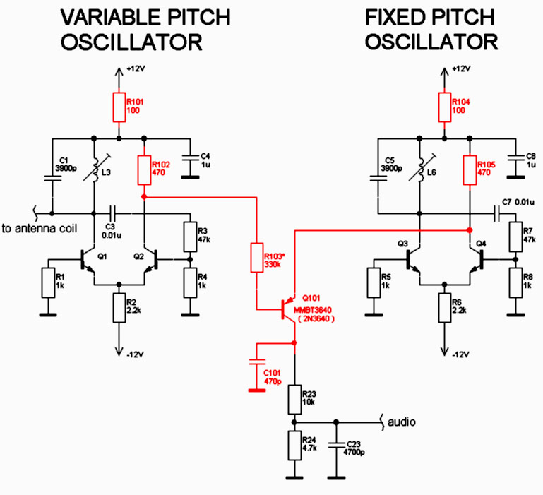
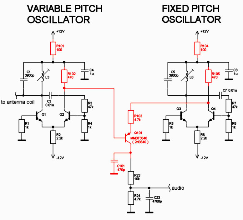
The improvements below are mostly suited for new design (based on EW schematics) than for existing EW boards (cutting traces and desoldering may be required).
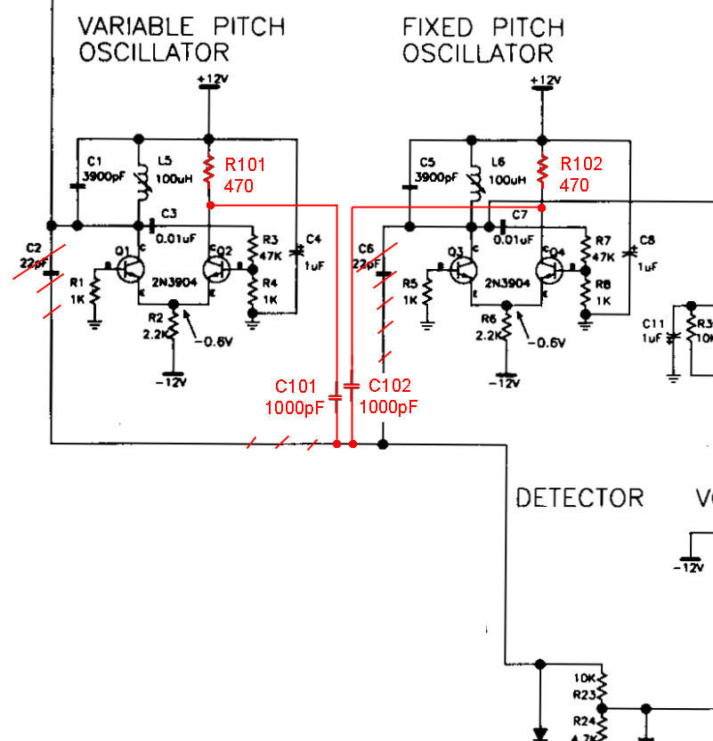
First version - using only 4 passive components (marked by red): 
The principle is simply: we get the RF signals not from the LC circuits but from the collectors of Q2 and Q4. With resistors R101 and R102, the transistors Q2 and Q4 are operated as some kind of output buffers.
Output RF voltages depend on R101 and R102, and with values of 470 ohm we get the 4 Volt peak-to-peak magnitude. The caps C101 and C102 are not critical and can be 200pF ... 0.1uF.
Waveforms from oscillators and mixer are presented below:
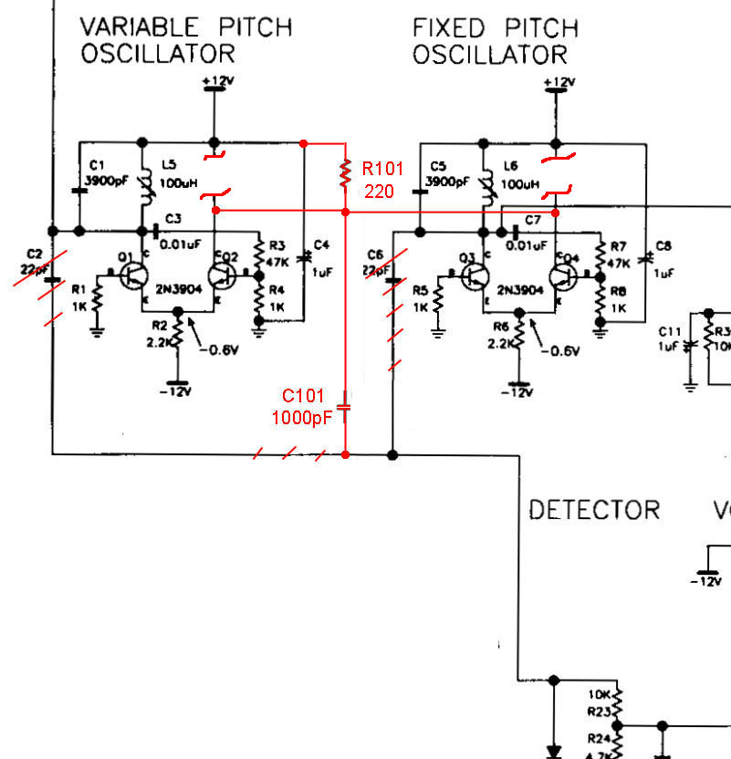
The next version is a simplified equivalent of first:

Results.
The original circuit had the lowest beat frequency 90Hz (before the oscilators will be locking); the new schematics allow notes going down 15...20Hz.


