Shielding Grounding and Tin Foil

Posted: 9/30/2016 8:42:26 PM
Fat Bob

From: Florida

Joined: 9/3/2016

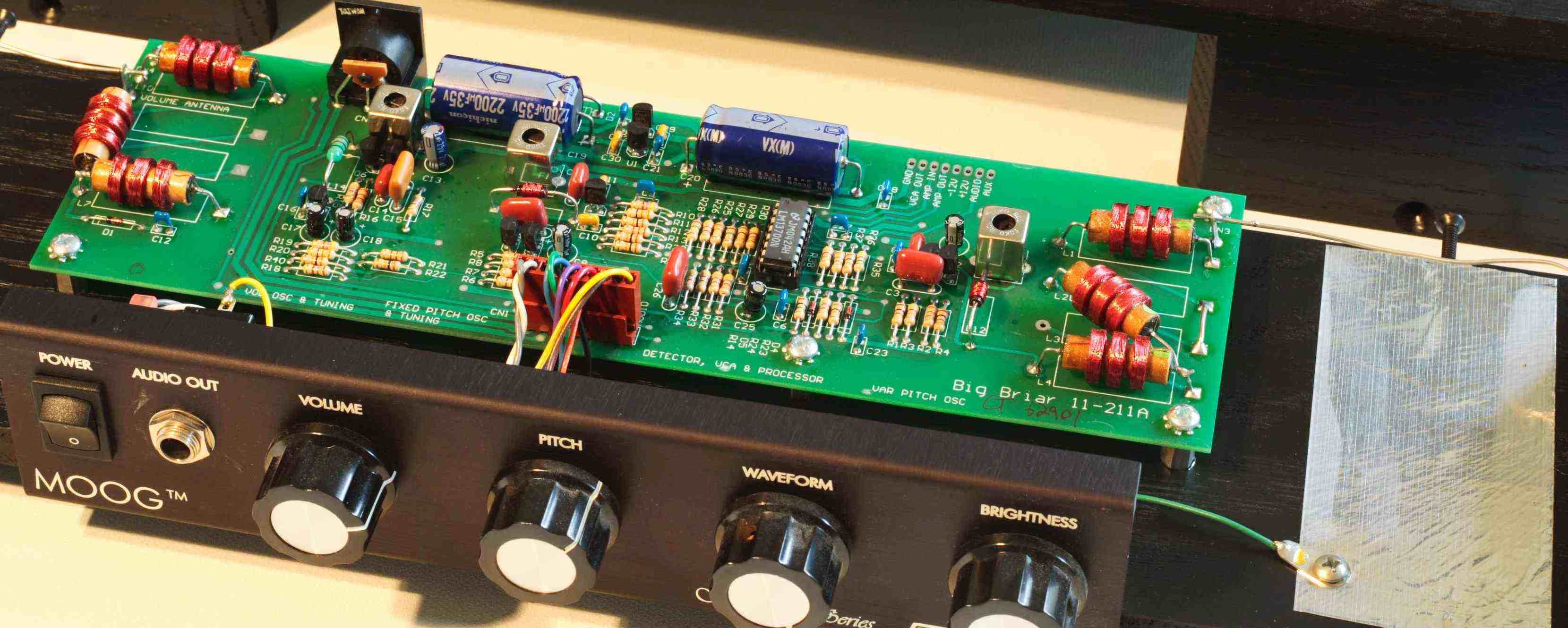
There is a hint in the Hot Rodding Article about putting a piece of Tin Foil under the pitch

antenna lead. Anyone know the size and approximate location for this. I haven't seen it

documented anywhere.


  Also there is conflicting info on whether or not to ground the coil shields. The may add

capacitance or pick up noise?


  Many of the earlier Theremins used metal chassis and AC transformers in their construction.

I have an audio transformer that is shielded I wonder if it would cause problems? I had planned

on using a metal chassis mainly to keep out interference  but if one side is tied to the AC ground

it is effectively 1/2 of the AC line and thus might not do much shielding. I understand it could add

capacitance and mess up the Oscillators but maybe if it is 1" from the board there is not much influence?
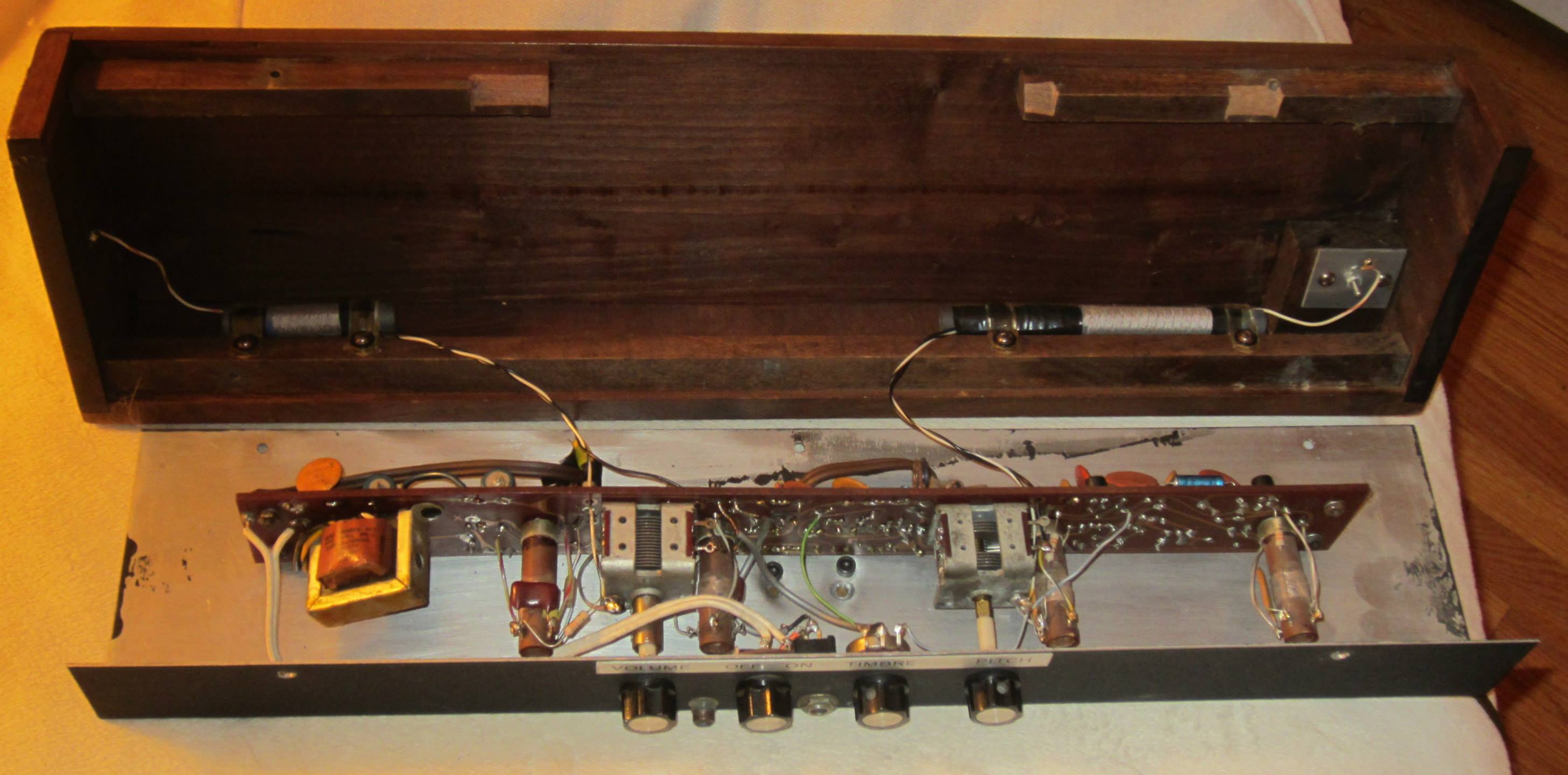
 AC and Metal Case

Anyone have experience in these matters who would like to comment?


Posted: 9/30/2016 10:28:26 PM
dewster

From: Northern NJ, USA

Joined: 2/17/2012

There is a hint in the Hot Rodding Article about putting a piece of Tin Foil under the pitch antenna lead. Anyone know the size and approximate location for this. I haven't seen it documented anywhere."  - Fat Bob

IIRC, my EWS had a standard width (2" ?) piece of aluminum tape under the pitch antenna lead, connected to ground.  Can't remember the length, maybe 3" or 4"?  It was in the section between the PWB and the right end of the case.  It's function is to add a small amount of variable C to the antenna side of things to help with tuning somehow (by bending the connecting wire closer to or farther away from the foil)?  I never found a use for it, but Thierry could probably explain it.

Also there is conflicting info on whether or not to ground the coil shields. The may add capacitance or pick up noise?

IMO it probably doesn't matter a lot either way, as the business end (capacitance sensing) is on the antenna side of the EQ coils.  It probably matters a lot more for designs which don't employ EQ coils.

Using metal to shield things probably isn't a terrible idea, but the most sensitive nodes to interference will still be exposed (pitch and volume antennas).

Posted: 9/30/2016 10:49:30 PM
Fat Bob

From: Florida

Joined: 9/3/2016

Thanks for the Reply Dewster!

I did manage to find a picture of the Tin Foil.

Tin Foil

I had a thought today. What if you took the shield off a coil and added a coil around it then you could modulate it with another source?

Posted: 10/3/2016 9:55:12 PM
Fat Bob

From: Florida

Joined: 9/3/2016

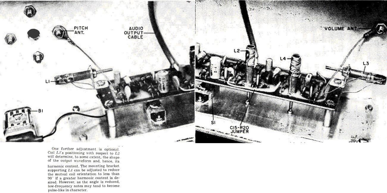
I found this in an old popular electronics. It faces the inductors in the fixed and variable oscillators

at 90 degrees but says you can adjust the harmonics by bending the bracket, sort of a physical

coupling scheme... (How about a knob tied to the bracket for on the fly adjustment?)

Pop Elec Nov 1967

Posted: 10/3/2016 11:20:09 PM
dewster

From: Northern NJ, USA

Joined: 2/17/2012

"(How about a knob tied to the bracket for on the fly adjustment?)"  - Fat Bob

If it is indeed adjusting the coupling between the coils, then why not use electronic means to vary the coupling rather than mechanical?  A variable resistor / inductor / capacitor somewhere between the two oscillators?

Posted: 10/5/2016 6:16:09 PM
Fat Bob

From: Florida

Joined: 9/3/2016

I'm looking at lots of different ways to vary the waveform. I'd like to see the resultant waveforms.

Soon I will be able to as I have a Melodia and an EW mostly complete. I have to get the boxes

together so I can attach the antenna's then I can experiment.

You must be logged in to post a reply. Please log in or register for a new account.