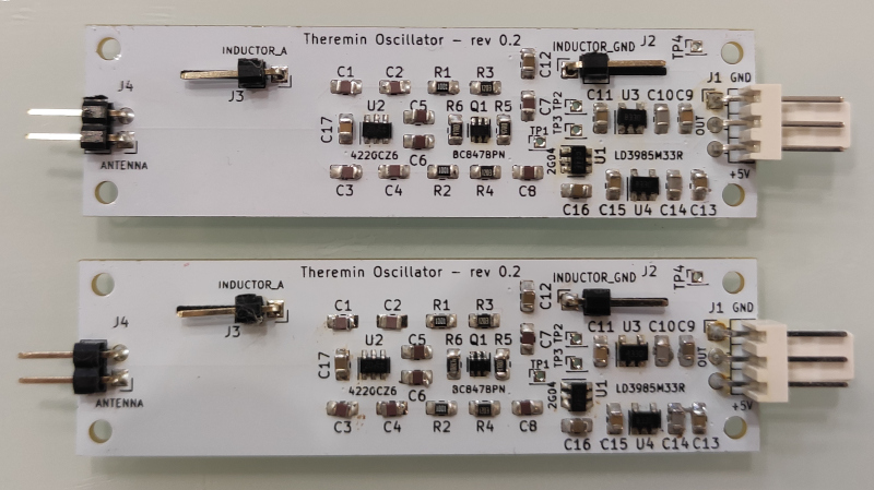
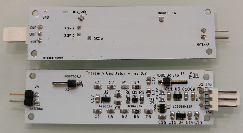
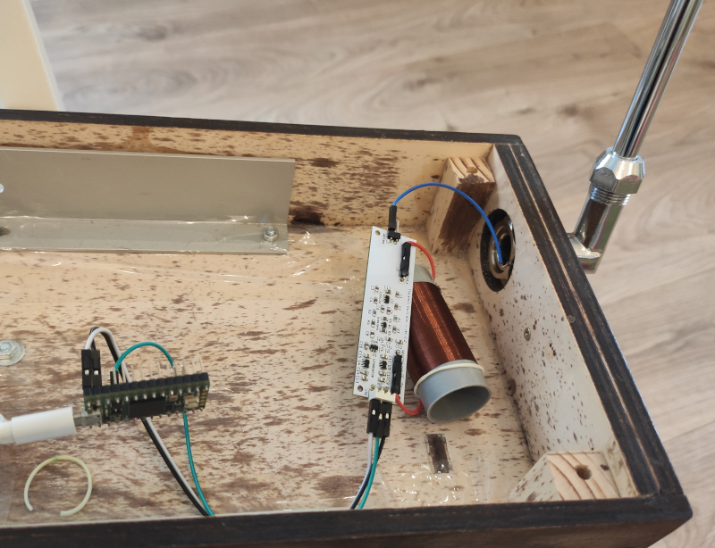
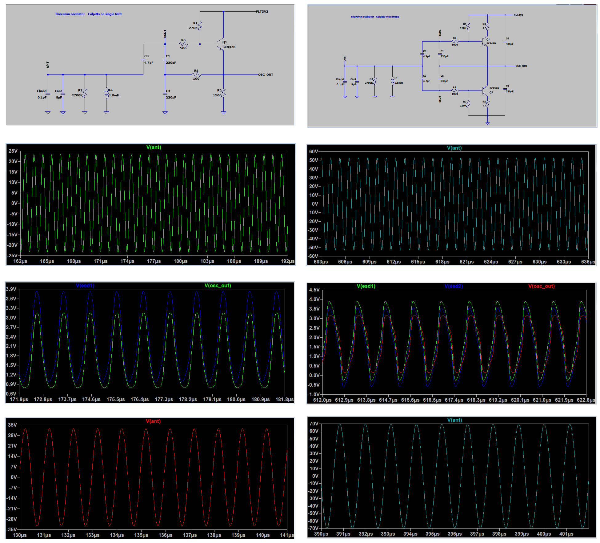
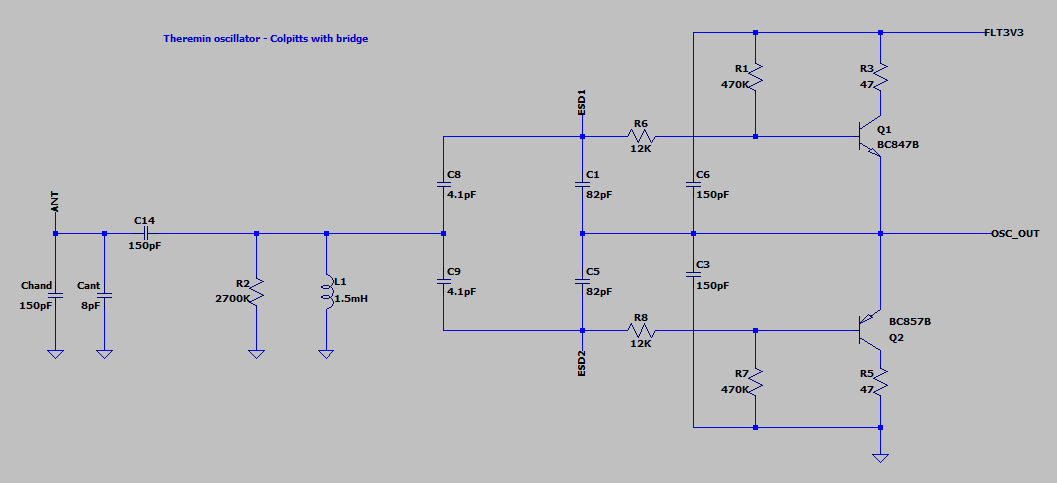
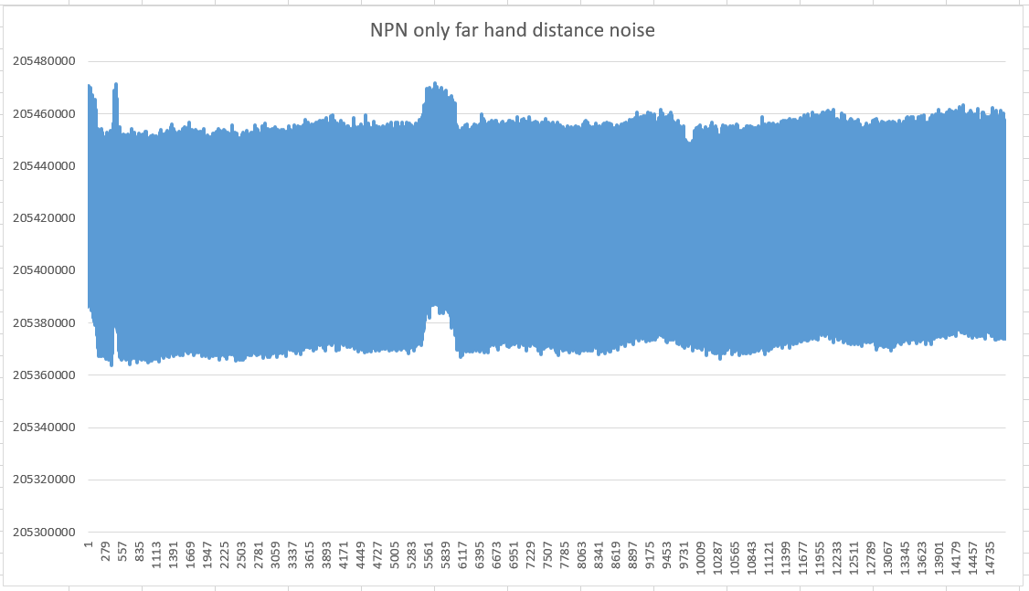
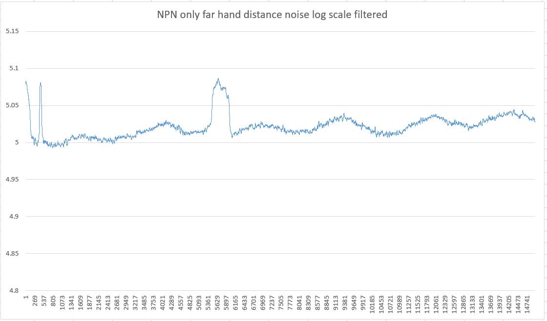
While oscillator boards are traveling from china, I'm planning the rest of Teensy4.1 based Theremin design.
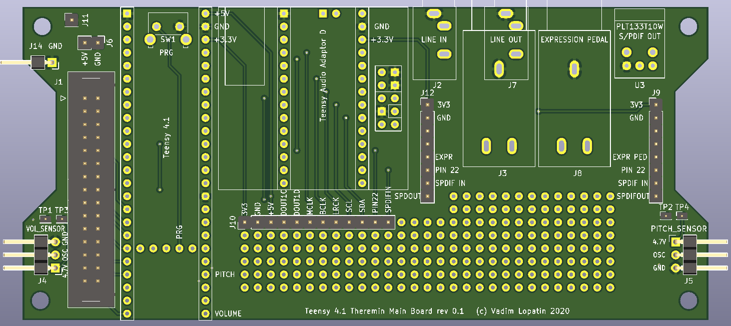
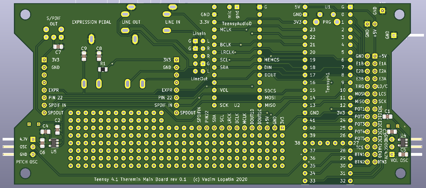
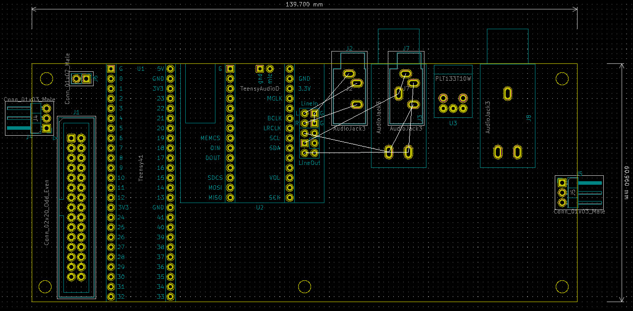
There will be two PCBs - main and display/control. Display board will be mounted under optimal angle for viewing.
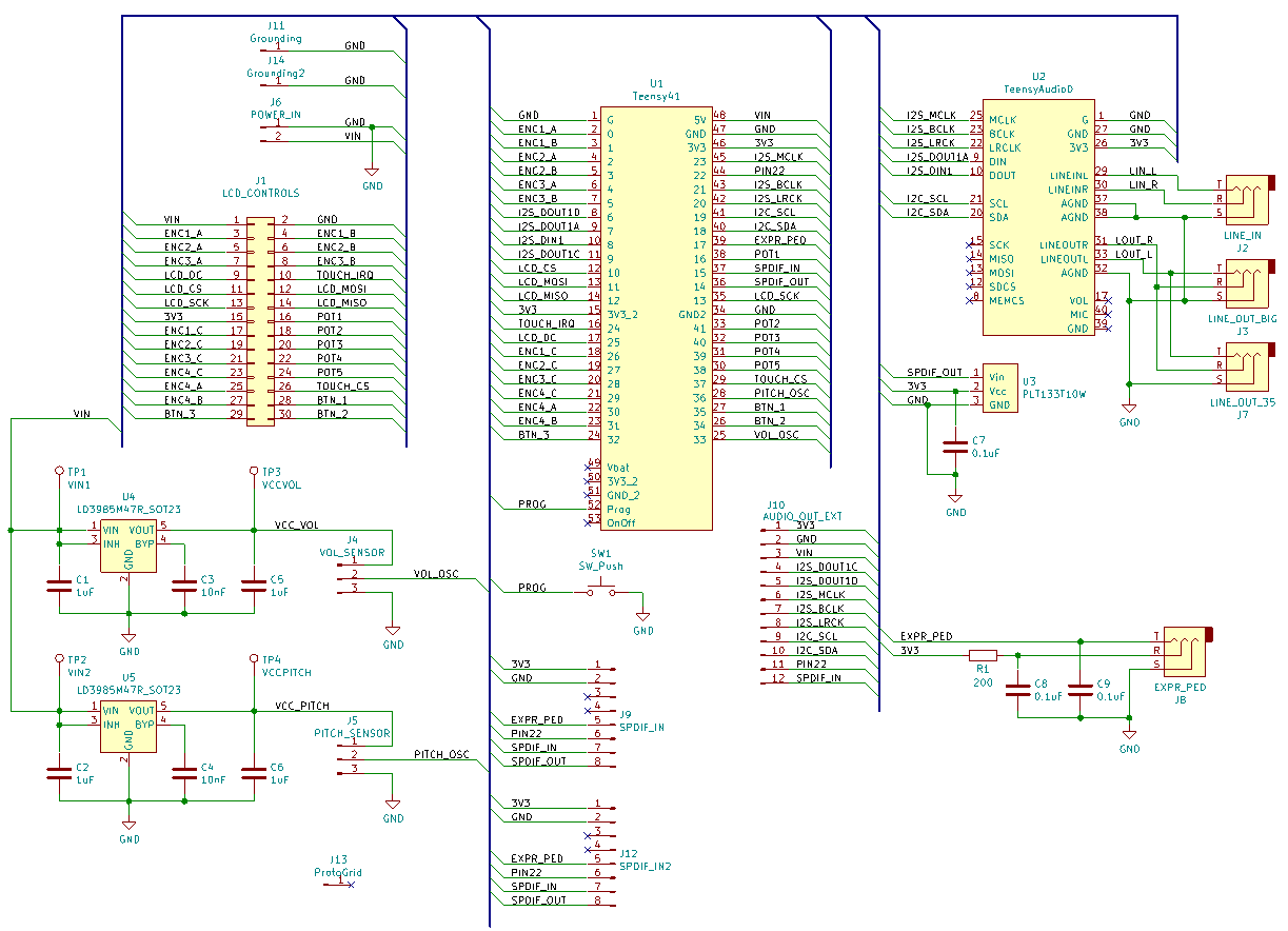
On main board, Teensy4.1 MCU and AudioAdaptor revision D are connected using pin headers.
Micro USB connector located on Teensy4.1 - for power, programming, connectivity (USB slave for Serial port and MIDI).
Phones out is located on audio adaptor board.
Line In - 3.5mm jack
Line Out - 6.35 or 3.5mm jack
S/PDIF optical out
Expression pedal 6.35mm jack (for connection of POT pedal)
Power DC In barrel socket can be mounted on rear panel and connected using 2 pins.
Grounding connector: can be mounted on rear panel and connected to gnd pin.
SDCard interface: on front panel - soldered on Teensy4.1
Optional USB Host, panel mounting, connected with cable.
Optional Ethernet, panel mounting, connected with cable.
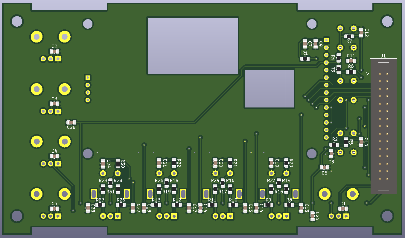
30pin IDC connector - for connecting display/controls board.
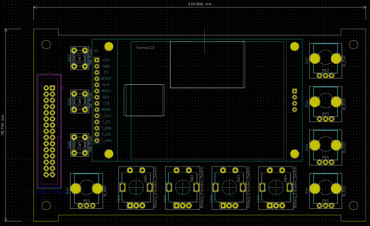
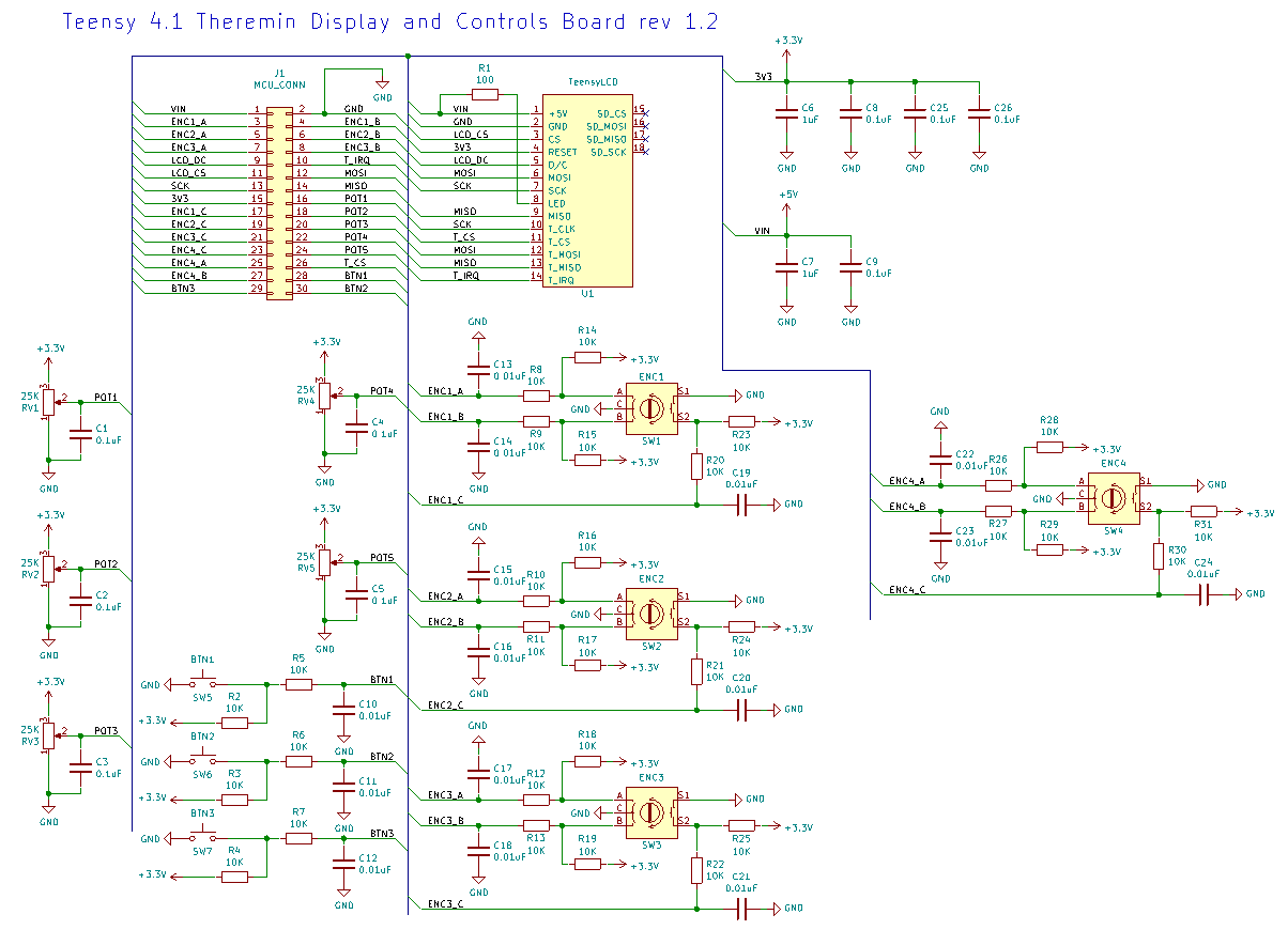
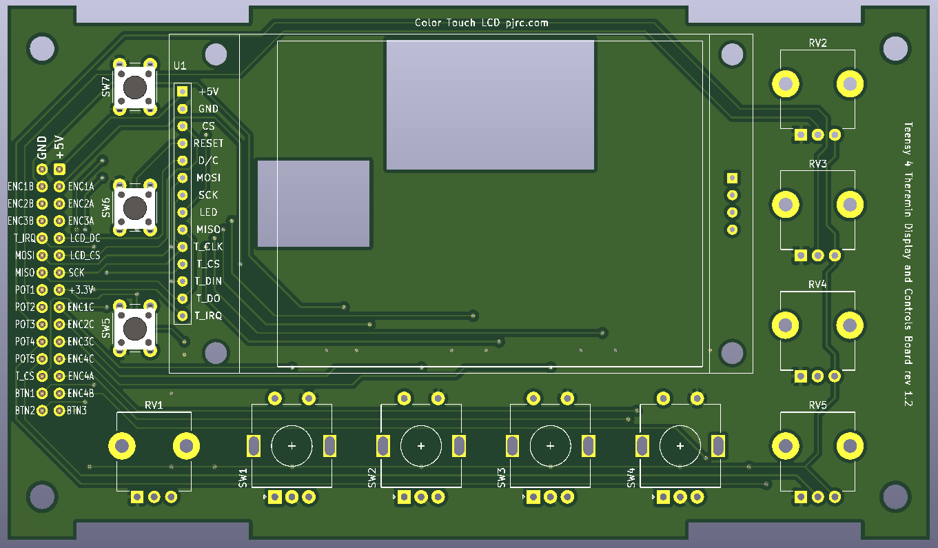
Designing LCD screen and controls board.
LCD is 2.8 inch 320x240 screen with SPI ILI9341 controller and resistive touch (SPI XPT2046).
I'm not sure what controls are required, so trying to place reasonable amount of different controls.
iMXRT1060 has 4 hardware rotary encoder support modules with internal debouncing. So it makes sense to use 4 encoders.
There are a lot of analog input pins available, so putting as many pots as possible (5 pots fit ok).
Several buttons may be useful (mute, calibrate, other functions). 3 or 4 may fit on left side.
30pin IDC connector additionally limits number of controls.
