Hi, Buggins! Please check your private messages. I can't get in touch with you ![]() .
.
Teensy 4.0 600MHz ARM Cortex M-7 MCU - ideal for digital MCU based theremin?
Created teensytheremin organization and theremin project on github.
Will put all schematics and firmware there.
Created github pages site with description of project - for documentation, build instructions, etc.
Project pages updated
Published Teensy 4.1 Theremin Main Board KiCAD project and schematics in PDF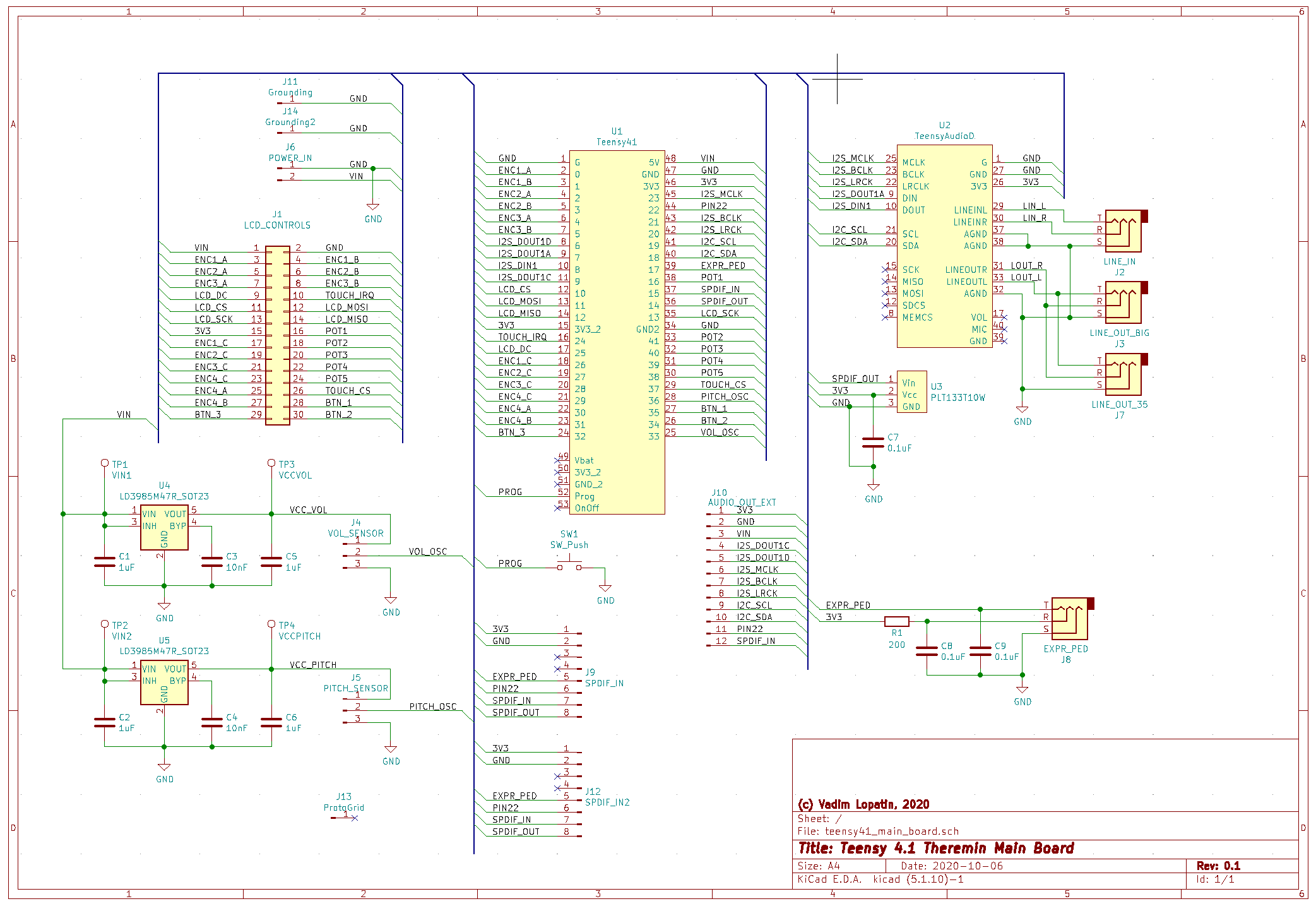
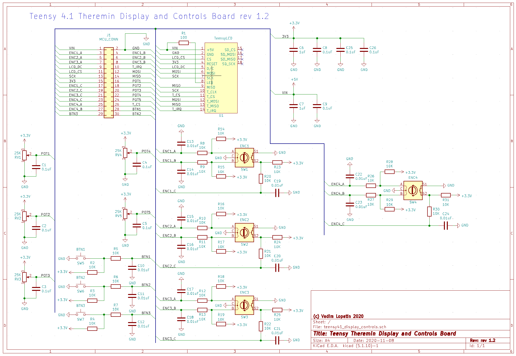
Published Teensy 4.1 Theremin Display and Controls Board KiCAD project and schematics in PDF
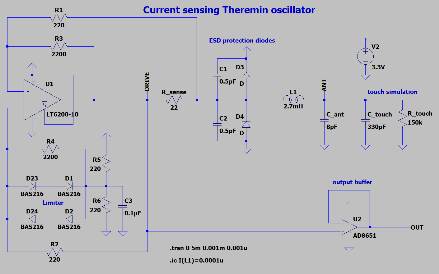
Previous LT1711 comparator based oscillator is unstable (starts oscillating at high frequency) when hand touches antenna.
New candidate for oscillator is described in this post
TODO: BOM and soldering instructions
Good article on mcu oscillators...
not sure if it will help, but I thought of it when I was reading this...
https://en.wikipedia.org/wiki/Numerically-controlled_oscillator?wprov=sfla1
Good article on mcu oscillators...not sure if it will help, but I thought of it when I was reading this...
It might be useful for FPGA theremin implementation - e.g. for generation of reference frequency in phase shift or pll based sensors.
Not for usual oscillator.
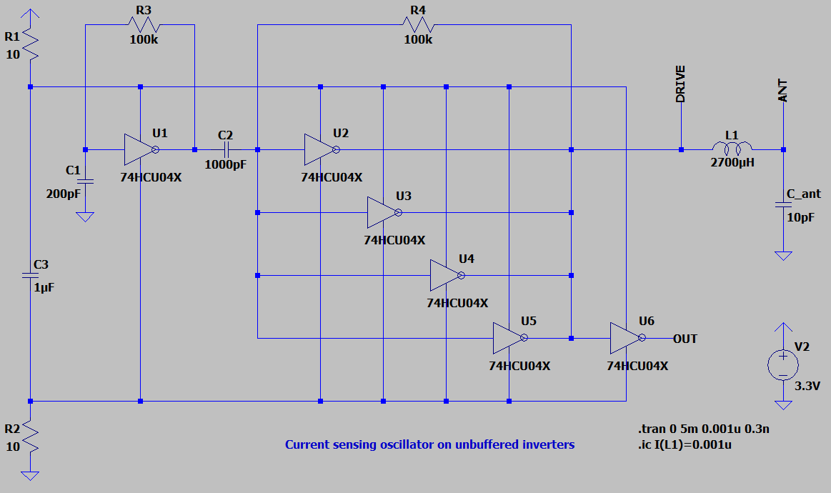
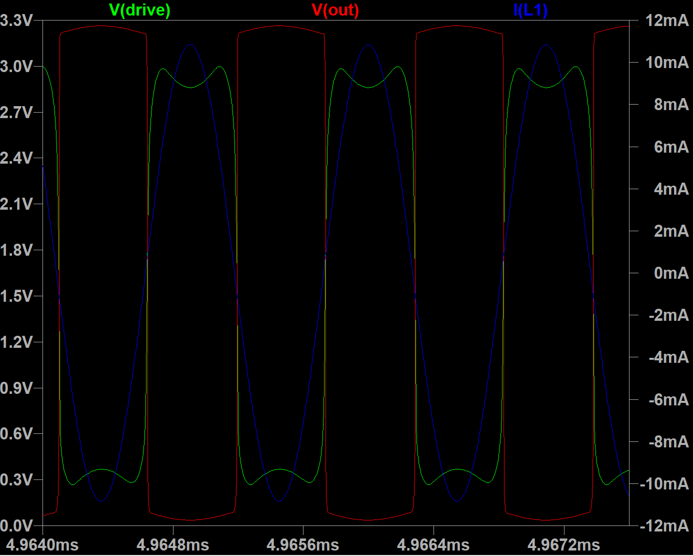
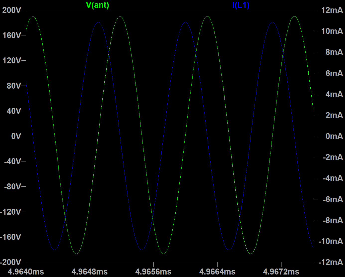
Unusual current sensing oscillator: details in this post
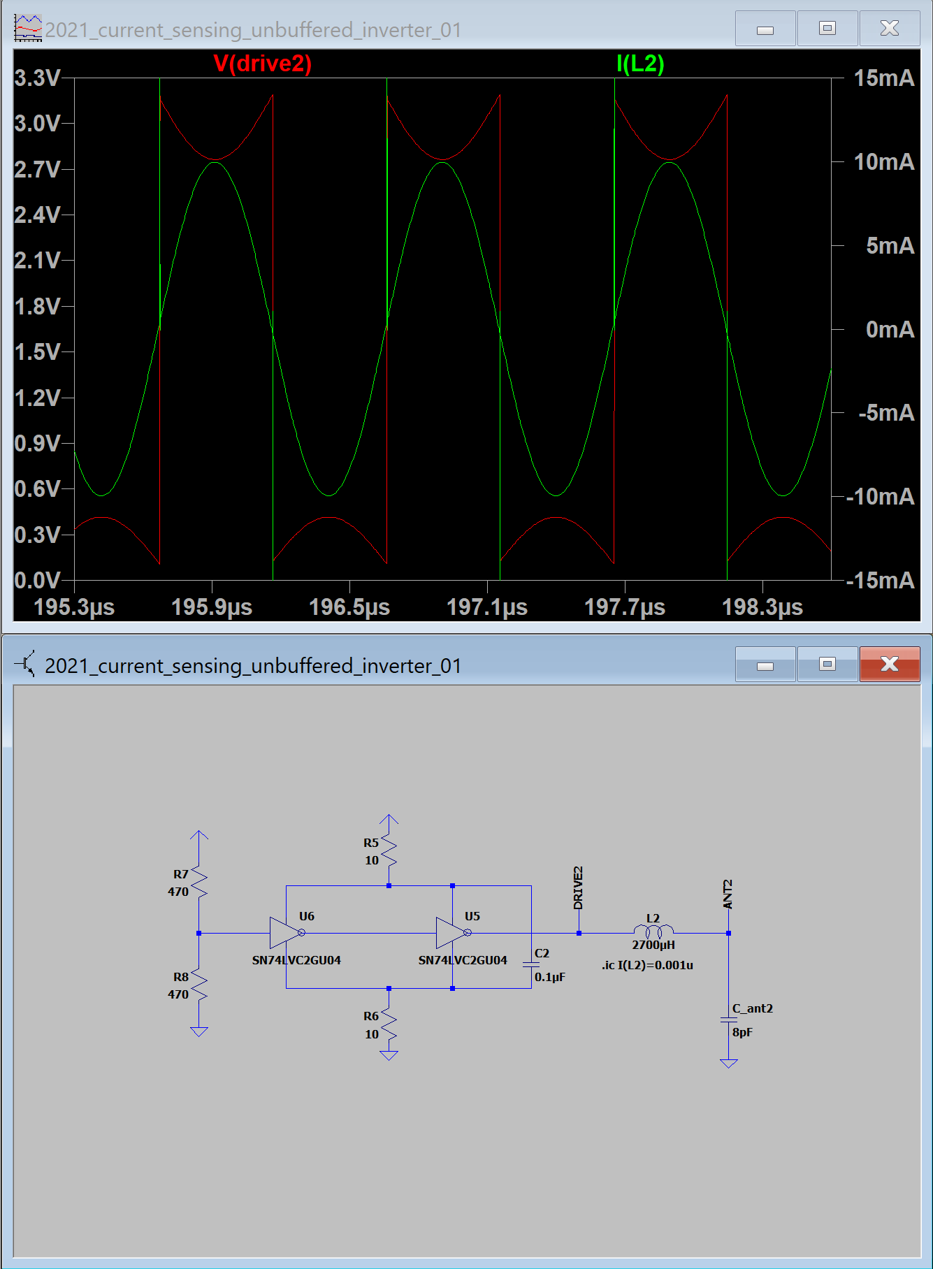
LTSpice model file is available on GitHub
SN74LVC2GU04 and other component models can be downloaded here
UPD: adding several output buffers in parallel provides bigger drive current. With 2 additional inverters in parallel with existing one gives 400Vpp on antenna.
LVC2GU04 model is a bit strange. Sometimes, provides empty signals - neither current nor voltage is visible in components connected with U04.
Does someone know where to find good lvc unbuffered inverter model?
Capacitor added to R7/R8 reference voltage sometimes helps.
Based on discussions with Eric at Wallin Oscillator thread, I'm starting Teensy 4.1 MCU based Digital Theremin from scratch.
Two ideas:
1) provide descent digital PLL theremin sensors based on cheap small FPGAs.
Gowin GW1N-LV1QN48C6/I5 chip with 1K LUTs is selected as FPGA, in prototype - as $6 Sipeed Lichee Tang Nano FPGA boards.
Analog front end boards will be placed on separate PCBs, for experiments with different types of front ends.
Two FPGAs will be used - one per sensor.
To minimize CPU resources usage for sensor data transfer from FPGAs to Teensy MCU, we will use i2s data channel.
Pitch and Volume sensor values will be packed as left/right channel data for each sample.
FPGA boards will be controlled from MCU using slave SPI interface - as a set of registers.
As well, it may be possible to upload FPGA configuration directly from Teensy using slave SPI interface - if MODE0 pin of GW1N is tied to +3.3V
2) use Android tablet for UI and controls - instead of small LCD, encoders and pots.
Teensy can be connected to android tablet's USB OTG e.g. as serial port device.
Application on Android will work as GUI and control.
Teensy MCU will spend most of CPU time on voice synthesis.
Planning PCB and cabinet.
I think plywood laser cut technology for cabinet fits ok here.
Cabinet dimenions: 400mm width, 74mm depth, ???mm height.
Inductors frame: 32mm polypropylene water pipe, 60mm length, 0.1mm / 0.125mm copper wire winding 35-40mm length.
Antennas: water/gas pipes similar to Etherwave ones.
Mic stand mount on bottom of cabinet - e.g. AtlasIED AD-11B Surface Mount Female Mic Flange 5/8-27 Thread
Legs to allow put cabinet on table.
Minimal size of main PCB - 200x60mm

Front panel connectors:
Line Out 6.35mm audio jack
Line In 3.5mm audio jack
Teensy MicroUSB connector
Rear panel:
Power In DC barrel jack: 5V 2A
S/PDIF Optical Out
S/PDIF Optical In
Teensy MicroSD card slot
Expression Pedal 6.35mm audio jack
Your layout is quite nice, I like the rotated use of the same board layout. You might want to rotate the pitch coil 90 degrees, which will minimize magnetic interaction (not a big deal IMO, but if it is free) and place the sensitive end of the pitch coil nearer to the antenna?
I still don't know what to think about using commercial computing HW & SW as an central integral component here. Those are some mighty shifting sands! Many times I've seen it ending up being a mistake (the use of PCs and Windows in particular) so I'm gunshy. But the economies of scale are hard to resist.
Vadim, I just implemented auto-unmute for ACAL and it seems to work OK. When the player initiates an ACAL (i.e. set the pitch and volume null points automatically) the volume is muted. After the ACAL is over, when the player moves their volume hand to a position that produces < -48dB then the volume is unmuted. For safety, the unmute only happens if the audio was unmuted before ACAL. Those (like myself) who play with non-traditional volume sense never even notice the action happening, as having arms back for ACAL naturally produces < -48dB post ACAL. Traditional volume sense is (cover your eyes / ears everyone!) crap.
Your layout is quite nice, I like the rotated use of the same board layout.
You might want to rotate the pitch coil 90 degrees, which will minimize magnetic interaction
(not a big deal IMO, but if it is free) and place the sensitive end of the pitch coil nearer to the antenna?
Good point. Will try to change layout to optimize connections and have 90 degrees between coils.
It's expecially important for Pitch sensor. Volume sensor does not require high sensitivity.
I still don't know what to think about using commercial computing HW & SW as an central integral component here.
Those are some mighty shifting sands! Many times I've seen it ending up being a mistake (the use of PCs and Windows in particular) so I'm gunshy.
But the economies of scale are hard to resist.
Not sure if I understood what do you mean... Connecting of theremin as a sensor to PC, and performing audio synthesis on it?
Theremin sensor may be connected to PC via USB, and provide axis data in realtime using serial or MIDI interface.
Tablet might work here, but I'm not sure if we can achieve low latency audio.
General purpose OS (linux, windows, macos) might be not enough realtime.
I like idea of using small but powerful MCU as key part for audio synthesis. It makes sense to have bare metal application or at least RTOS.
Teensy board is probably powerful enough. It would be possible to use more powerful hardware, e.g. Raspberry PI board.
Devices like RPI have HDMI + USB which allow to connect a lot of compatible touch displays of any size.
RPI Zero has a lot of SDRAM, and 1GHz single core CPU. But it's slower than Teensy4 which has tightly coupled SRAM, and has predictive performance, w/o cache misses.
But recently, RPI Zero 2 became available. It has quad cores, which may be enough for realtime sound synthesis.
So, instead of Teensy4+tablet, RPI Zero 2 + LCD touch screen may be used.
Vadim, I just implemented auto-unmute for ACAL and it seems to work OK.
When the player initiates an ACAL (i.e. set the pitch and volume null points automatically) the volume is muted. After the ACAL is over, when the player moves their volume hand to a position that produces < -48dB then the volume is unmuted. For safety, the unmute only happens if the audio was unmuted before ACAL. Those (like myself) who play with non-traditional volume sense never even notice the action happening, as having arms back for ACAL naturally produces < -48dB post ACAL.
Traditional volume sense is (cover your eyes / ears everyone!) crap.
I like your reverse (or natural?) volume control behavior.
Why classic theremin uses far=loud approach? Probably, it was easy to implement in analog theremin.
Regarding far distance muting post from D-lev thread - about what volume level should we consider as muted. I think, it makes sense to add non-linear distance-to-dB curve at far distances. Starting with distance=-48dB, decrease volume at higher rate - leading to
Thinking about cabinet design. Acrylic cabinet made with laser cut will look good enough.
Does someone try to use CAD for laser cut design? Trying to learn FreeCAD...
You must be logged in to post a reply. Please log in or register for a new account.


