CMOS555Theremin - a simple analog DIY Theremin

Posted: 9/5/2023 9:25:26 AM
elektrouwe

Joined: 9/5/2023

after building one of the CMOS555-Theremin kits during the SGMK home made week my friend Urs from Open Theremin suggested to publish the design here.
Meanwhile I have started to fill my web site, so here is the link:
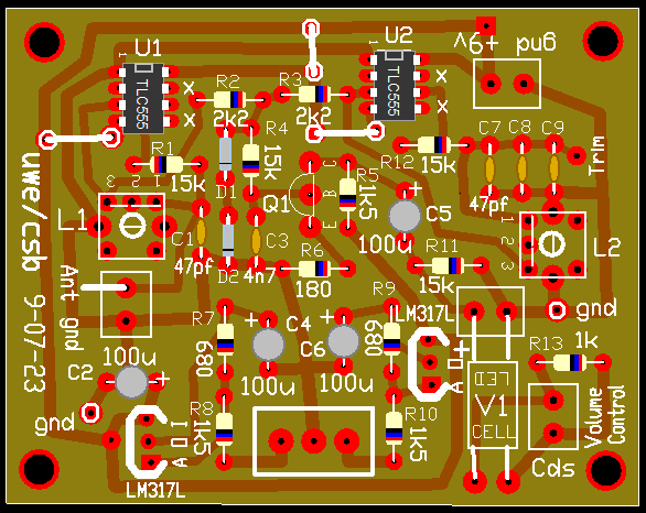
CMOS555-Theremin

Have fun building and playing it !

I do not sell PCBs, kits nor finished Theremins.
upcoming workshop: Dresden,Germany Sept.7..9 @ circuit control 2023
(this will be the last workshop for 2023, because the 1st batch of 60 PCBs is gone now)

Offer for EU residents : if you want to teach your own CMOS555-Theremin NONPROFIT workshop, you can have 10..30 classroom sets of these 330uH coils for free (exept shipping fee). Drop me a line if you are interested.


Posted: 9/5/2023 3:55:46 PM
oldtemecula

From: 60 Miles North of San Diego, CA

Joined: 10/1/2014


Great Job!

I am all in on DIY and this looks like a fun project to make. It would be better represented if you called your build a "gesture controlled synthesizer". The Theremin is a beautiful musical instrument and not a Halloween sound generator. Calling your design a theremin is like a child convinced his simple keyboard is a grand piano. Paul Tanner was first to catch hell for this miss use of the Theremin family name, though he only called his device "Paul's Box".

Edit: Your design has great sensitivity so the 555 method might be modified into a workable proximity volume control?

There are many gesture controlled synthesizers on the market today exploiting the Theremin name and I have fear people will soon forget the authentic "Theremin Phenomenon" which has its own unique sound or timbre, not a flute, whistle or worse. This sample uses the authentic theremin principle with $100 in modern day solid state parts.

- Modern Theremin Sound

This design is now being studied at the Massachusetts Institute of Technology or MIT in how I got my results. I know of no one after 20 years of being publically posted as a DIY project duplicating my research. What you hear was performed by Valery Shamarin in St Petersburg Russia. My original instrument now resides with the family of Lev Sergeyevich Termen as of Christmas 2020.

Christopher

Posted: 9/6/2023 9:25:26 AM
dewster

From: Northern NJ, USA

Joined: 2/17/2012

Greetings elektrouwe, and thank you for showing us your design work!  

Your oscillator is quite novel!  I'm looking at the schematic and it seems R1 has no other component to form a voltage divider of the reported >150Vpp at the antenna?  I'm guessing it relies on the CMOS input ESD clamping diodes, and is therefore mainly a current limiter for them?

Differential voltage supplies is a clever approach to tuning zero beat!

Posted: 9/6/2023 9:52:57 PM
JPascal

From: Berlin Germany

Joined: 4/27/2016

The idea of using common 555 sine wave oscillators for a theremin, providing circuit boards and using inexpensive components is really great for workshops with children and other electronics beginners! Thanks for that offer and I hope there are many interested.

I wondered why the sound isn't that good and suspected that the coupling was too strong. But now I think the pin 3 out does not have a sine signal form, more alternating pulses?

Posted: 9/6/2023 10:33:25 PM
elektrouwe

Joined: 9/5/2023

Thanks for your comment, Christopher. I think it's ok to call an instrument a Theremin if it is technically close to the original. In this case we have the capacitive detuning of an LC oscillator via antenna and the heterodyning principle. That's closer to the original than a digital Theremin or CV type gesture controller. I can understand your worries about the fade of the original Theremin Phenomena. But I think this is a Zeitgeist problem and this Forum is not the right place to debate it.
" Your design has great sensitivity so the 555 method might be modified into a workable proximity volume control?"
I guess it is possible. I already did some LTSPICE simulation during the design phase, but decided to not include volume control to keep this instrument simple and beginner friendly for DIY music electronic workshops which is my main interest and not developing classic style Theremins.
cheers from the wild south of Germany, Uwe

Posted: 9/6/2023 10:57:21 PM
elektrouwe

Joined: 9/5/2023

... R1 has no other component to form a voltage divider of the reported >150Vpp at the antenna?  I'm guessing it relies on the CMOS input ESD clamping diodes, and is therefore mainly a current limiter for them?

Greetings Dewster ! yes, the "only R1" variant is the result of an empirically reduction of component count. In my simulations I started with a capacitive divider feeding the Schmitt-Trigger + a resistor between in and out to provide startup as RC oscillator. When enough energy is pumped into the LC tank, it "overwrites" the RC frequency due to higher LC resonant voltage. But finally the simpler 1 resistor + protection diode clipping turned out to be the best solution. Due to the DC feedback it has an inherent startup guarantee and by varying R1 I could  select sensivity ( antenna voltage) independent of frequency.

Posted: 9/6/2023 11:16:56 PM
elektrouwe

Joined: 9/5/2023

... I wondered why the sound isn't that good and suspected that the coupling was too strong. But now I think the pin 3 out does not have a sine signal form, more alternating pulses?

The sound of the demo video is bad, because it was recorded from a 1" speaker powered cinese 1W amp whith the smartphone :-)
Goal of this video was to show the high sensivity of this low cost Theremin and not the sound. I could compare the CMOS555Theremin with a Moog Etherwave and an Open Theremin V4 and found the sound (experienced) and playability (noob)  not too different.
Pin3 outputs a square which is a bit deformed due to the output resistance (mainly of the p-channel MOSFET). Mixing 2 RF-squares gives a triangle as difference+ some fixed frequency lowpass filtering. So bass frequencies have more overtones than the higher octaves.

Posted: 9/7/2023 2:23:27 AM
oldtemecula

From: 60 Miles North of San Diego, CA

Joined: 10/1/2014

Your build is growing on me and yes call it a theremin, I am getting anal in my old age.

I have not done a electronic project in several years as Father Time is doing a number on me. I can sit in a chair and draw on my laptop, that’s about it as legs barely work.

Thinking of modifying your output of Q1 to turn off the LED in a Vactrol. I need to study a live build & Frequency to Voltage Pulse width behavior.

My own Volume control design I have never been happy with as it is overly complicated and I see possibilities in the response of your design.

I did lay your design out on a single sided board with my 20 year old software. The board will use a few jumper wires for power only. I have a new theremin friend I might encourage him to build it. I used the footprint of an IF can as they are adjustable and 360uh. If the frequency is critical I will change the 47pf to 43pf.

  Datasheet

I wish you the best.

Christopher

- Full version with optional Volume add-on found here -


Needs a final proof for errors, will convert Gerber files to an iron-on PDF

Q1 output to drive Vactrol LED needs development, going to try an LM2907 on this first layout.

I am too dumb to use LTSpice.

Posted: 9/7/2023 10:18:53 AM
dewster

From: Northern NJ, USA

Joined: 2/17/2012

"yes, the "only R1" variant is the result of an empirically reduction of component count."  - elektrouwe

That makes sense.  The D-Lev can actually function this way as well, removing the lower C on the C divider, though it messes with the phase at resonance, and so lowers the voltage swing.

"In my simulations I started with a capacitive divider feeding the Schmitt-Trigger + a resistor between in and out to provide startup as RC oscillator. When enough energy is pumped into the LC tank, it "overwrites" the RC frequency due to higher LC resonant voltage."

Fascinating!

"But finally the simpler 1 resistor + protection diode clipping turned out to be the best solution. Due to the DC feedback it has an inherent startup guarantee and by varying R1 I could  select sensivity ( antenna voltage) independent of frequency."

I haven't simulated your oscillator, but I imagine that lower values of R1 would increase LC damping?  R1 may also vary the drive / antenna phase?  Higher Q inductors are more sensitive to phase drive error.  Guaranteed startup is important, and in this circuit I imagine that the feedback would necessarily need to be DC for that to happen?

How is the drift over temperature / time?

Posted: 9/7/2023 12:23:02 PM
elektrouwe

Joined: 9/5/2023

..I did lay your design out on a single sided board with my 20 year old software. The board will use a few jumper wires for power only. I have a new theremin friend I might encourage him to build it...

Wow, what a fast development! I'm looking forward to hearing about your results. Fingers crossed your Theremin friend can do it soon :-)

You must be logged in to post a reply. Please log in or register for a new account.