"Let me see if I've got this straight: with your upside down topology you're tuning the LC tank to keep it oscillating at a fixed frequency? You do this I presume by subtracting capacitance from the tank as the hand approaches?" - Dewster
Effectively changing the oscillator somehow, in order to compensate for hand capacitance and therebye keep it frequency constant - If you remember (I cant find where - probably on your massive digital thread somewhere ;-) all sorts of schemes were examined for combining voltage control and capacitive control..
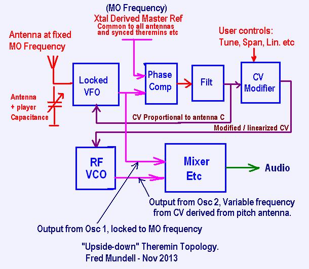
But yes - in its (probably) simplest form, the oscillator could maintain lock with the reference oscillator by adjusting the antenna capacitance so that this was kept constant as the hand capacitance changed.
I have copied the diagram from the above thread just for simplicity:

The "CV Proportional to antenna C" is what is used to maintain (lock) the VFO frequency - so its title could be "wrong" if this CV is used to effectively lock the antenna C to a fixed value.. Also, the little I played with this topology, I found that taking the MO frequency to the mixer seemed to give better results than taking the signal from the locked VFO.
The alternative ways of controlling the VFO are by using synchronous switched capacitor techniques, your phase shifting techniques, varying inductance via electronic means, standard ways are things like varicaps, and the method I will probably use if I go anywhere with this is my opto-coupler varicap "crazy idea" which actually seems to work well! - Another (more expensive but perhaps better) idea is using these new photodiode array optoisolators (one gets an isolated voltage source whose voltage is proportional to LED current) driving varicaps - This scheme overcomes a lot of problems AFAICS, but I only recently bought some of these (expensive because theyr new) parts and have only just started playing with them.
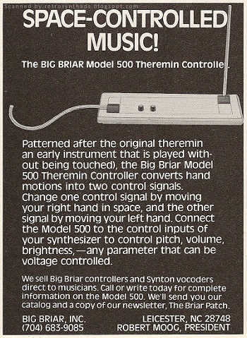
If one was to eliminate the RF VCO and mixer, and take the modified CV to an analogue VC synthesiser, from what Thierry was saying, this might be quite close to how the 91 operates... And who knows, if one just took the CV out, it may be similar to how the Big Briar controller operated.
The 4046 is a lovely little all-in-one PLL IC, but I have found that the phase comparator is the most critical component, and I have been playing with my own design which combines frequency and phase comparison with an analogue 'curve shaper' - this gives a tiny bit of 'portamento' (<100us) to the correction signal - If I go this route though, there would be a slight variation of the frequency of the antenna, as the oscillator would not be tightly locked to the MO, it would be doing 'catch up' if there was a big change in hand capacitance - I havent built it yet, but expect only tiny frequency deviation.
I have, however, moved onto a different project now - although I might use this topology in that, the real advantages of this topology (adjustable span and linearity) are wasted on my new project - I would only use this topology with my new instrument if I decide to combine this with a conventional theremin (my new project is a capacitive ribbon instrument, which I hope will contain a complete multi-mode theremin voicing scheme (heterodyning and mixed signal) - If I was to add sockets for a conventional rod and loop, and use my upside down topology, I could have an instrument that combines both playing methods - Only the upside down topology could do this, because linearity profiles would need to be changed easily depending on whether ribbon or antenna sensors were used (the ribbon is shaped for "mechanical" linearization and has fixed note spacing, so if antennas are fitted, some electronic linearization / span control will be required for these).
Fred.


