Big Briar 91 series Technology ?

Posted: 7/20/2008 11:22:29 PM
FredM

From: Eastleigh, Hampshire, U.K. ................................... Fred Mundell. ................................... Electronics Engineer. (Primarily Analogue) .. CV Synths 1974-1980 .. Theremin developer 2007 to present .. soon to be Developing / Trading as WaveCrafter.com . ...................................

Joined: 12/7/2007

This is a continuation from the hijacked Theremin Amp thread..

[b]This "doesn't use heterodyning ..." begs the question "what does it use instead?"[/b]

Does anyone have schematics (or link to) for 91 series? I would be most interested in seeing what is being done!

From the data (tech spec, sales sheet etc) I have seen, the tone generation claims to use "synthesiser technology" - this, particularly from Moog, almost certainly means Voltage Controlled -

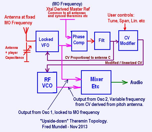
I suspect (this is how I would probably do things if I wanted voltage control from theremin sensing circuits, and never had the chips I use) that both antennas have a single oscillator each (no reference oscillators), and frequency (capacitance change) detection is performed in the same manner as used for volume antennas in most theremins (see volume antenna circuit in EW).

The above would give a voltage proportional to capacitance for each antenna.. volume antenna voltage would drive the VCA as per EW, Pitch antenna voltage would probably be processed to provide as-close-to-linear a profile as could be achieved (this would probably be a log, or some other non-linear function implemented by P-N junction of a transistor).

The linear CV would then be taken to a standard VCO+VCF circuit to produce the tone..

But the above is all guessing - I would love to see Moog's schematics on this - I never realised he had gone down this route and actually released an instrument based on this method.

Was the 91 series popular? Do people like it as much as heterodyning theremins, or not even notice the difference?
Posted: 3/7/2014 9:15:35 PM
Ziman

Joined: 12/3/2011

Hi,

I found this thread while searching the web for the basic principle behind the Big Briar 91.

Have you found the answer since the previous post?


Posted: 3/7/2014 10:20:59 PM
FredM

From: Eastleigh, Hampshire, U.K. ................................... Fred Mundell. ................................... Electronics Engineer. (Primarily Analogue) .. CV Synths 1974-1980 .. Theremin developer 2007 to present .. soon to be Developing / Trading as WaveCrafter.com . ...................................

Joined: 12/7/2007

Hi Ziman,

No - No real data.. My understanding now is that both pitch and volume oscillators are fixed frequency, and that the circuitry uses some means (amplitude or phase or both) to turn the change in antenna circuit resonance frequency (due to changing hand capacitance) into voltage to drive synth circuits, and I think there was some discussion on Levnet (google group)..

One thing is certain I believe - This is that this theremin is fully voltage controlled and does not use heterodyning at any point in its topology.

But I have seen no hi-res photos from which to extract any useful data and no schematics - so if you do find ANYTHING I would be really interested..

There are people out there who know, but arent making this stuff public - which is a real criminal shame IMO because it holds back a possible route to advancement of the art.

Fred. 


Posted: 3/7/2014 11:04:04 PM
dewster

From: Northern NJ, USA

Joined: 2/17/2012

"No - No real data.. My understanding now is that both pitch and volume oscillators are fixed frequency, and that the circuitry uses some means (amplitude or phase or both) to turn the change in antenna circuit resonance frequency (due to changing hand capacitance) into voltage to drive synth circuits, and I think there was some discussion on Levnet (google group).."  - FredM

Fred, this sounds very much like your "upside down" oscillator!

Posted: 3/8/2014 4:07:55 AM
FredM

From: Eastleigh, Hampshire, U.K. ................................... Fred Mundell. ................................... Electronics Engineer. (Primarily Analogue) .. CV Synths 1974-1980 .. Theremin developer 2007 to present .. soon to be Developing / Trading as WaveCrafter.com . ...................................

Joined: 12/7/2007

LOL ;-)

Upside down oscillator ?

I suppose .... I was thinking in terms of an "upside-down topology" rather than an "upside down oscillator".. But I suppose a variable oscillator whose frequency is locked to a reference oscillator via a PLL, so that it cant vary, but simply outputs a varying error signal proportional to how much it would vary if it could...

Hmmm ... I suppose one could call that an "upside down" VFO ;-)

One thing is for sure though, thats not how the 91 works! .... The 91 doesnt use heterodyning - my upside down topology has fixed frequency on the antenna (the variable oscillator whose frequency isnt allowed to vary) but as the error signal drives a VFO that is allowed to vary, and is heterodyned with the locked oscillator to produce the audio ;-)

I love heterodyning! - Even if it didnt have any sonic advantage, I think id still be in love with it, just because its so quirky!

Fred.

Posted: 3/8/2014 4:20:41 AM
FredM

From: Eastleigh, Hampshire, U.K. ................................... Fred Mundell. ................................... Electronics Engineer. (Primarily Analogue) .. CV Synths 1974-1980 .. Theremin developer 2007 to present .. soon to be Developing / Trading as WaveCrafter.com . ...................................

Joined: 12/7/2007

http://www.thereminworld.com/Forums/T/29201/possibly-a-new-theremin-topology-and-links-to-related-background

Many thanks Dewster - You reminded me of this thread! (oops - I now remember why I forgot it..)

There are some photos of the 91 on this. and details from Thierry.

Also, on TW's home page at the moment theres a picture of a Big Briar (ancient Moog) controller theremin instrument which outputs CV

This instrument isnt big enough to have big coils... I wonder if its in any way related to the 91 ?

Posted: 3/8/2014 2:16:34 PM
dewster

From: Northern NJ, USA

Joined: 2/17/2012

"I was thinking in terms of an "upside-down topology" rather than an "upside down oscillator""  - FredM

Let me see if I've got this straight: with your upside down topology you're tuning the LC tank to keep it oscillating at a fixed frequency?  You do this I presume by subtracting capacitance from the tank as the hand approaches?

"This instrument isnt big enough to have big coils... I wonder if its in any way related to the 91 ?"

I don't know, but I wish I could purchase that case in small quantities!

Posted: 3/8/2014 3:03:51 PM
FredM

From: Eastleigh, Hampshire, U.K. ................................... Fred Mundell. ................................... Electronics Engineer. (Primarily Analogue) .. CV Synths 1974-1980 .. Theremin developer 2007 to present .. soon to be Developing / Trading as WaveCrafter.com . ...................................

Joined: 12/7/2007

"Let me see if I've got this straight: with your upside down topology you're tuning the LC tank to keep it oscillating at a fixed frequency?  You do this I presume by subtracting capacitance from the tank as the hand approaches?" - Dewster

Effectively changing the oscillator somehow, in order to compensate for hand capacitance and therebye keep it frequency constant - If you remember (I cant find where - probably on your massive digital thread somewhere ;-) all sorts of schemes were examined for combining voltage control and capacitive control..

But yes - in its (probably) simplest form, the oscillator could maintain lock with the reference oscillator by adjusting the antenna capacitance so that this was kept constant as the hand capacitance changed.

I have copied the diagram from the above thread just for simplicity:

The "CV Proportional to antenna C" is what is used to maintain (lock) the VFO frequency - so its title could be "wrong" if this CV is used to effectively lock the antenna C to a fixed value.. Also, the little I played with this topology, I found that taking the MO frequency to the mixer seemed to give better results than taking the signal from the locked VFO.

The alternative ways of controlling the VFO are by using synchronous switched capacitor techniques, your phase shifting techniques, varying inductance via electronic means, standard ways are things like varicaps, and the method I will probably use if I go anywhere with this is my opto-coupler varicap "crazy idea" which actually seems to work well! - Another (more expensive but perhaps better) idea is using these new photodiode array optoisolators (one gets an isolated voltage source whose voltage is proportional to LED current) driving varicaps - This scheme overcomes a lot of problems AFAICS, but I only recently bought some of these (expensive because theyr new) parts and have only just started playing with them.

If one was to eliminate the RF VCO and mixer, and take the modified CV to an analogue VC synthesiser, from what Thierry was saying, this might be quite close to how the 91 operates... And who knows, if one just took the CV out, it may be similar to how the Big Briar controller operated.

The 4046 is a lovely little all-in-one PLL IC, but I have found that the phase comparator is the most critical component, and I have been playing with my own design which combines frequency and phase comparison with an analogue 'curve shaper' - this gives a tiny bit of 'portamento' (<100us) to the correction signal - If I go this route though, there would be a slight variation of the frequency of the antenna, as the oscillator would not be tightly locked to the MO, it would be doing 'catch up' if there was a big change in hand capacitance - I havent built it yet, but expect only tiny frequency deviation.

I have, however, moved onto a different project now - although I might use this topology in that, the real advantages of this topology (adjustable span and linearity) are wasted on my new project - I would only use this topology with my new instrument if I decide to combine this with a conventional theremin (my new project is a capacitive ribbon instrument, which I hope will contain a complete multi-mode theremin voicing scheme (heterodyning and mixed signal) - If I was to add sockets for a conventional rod and loop, and use my upside down topology, I could have an instrument that combines both playing methods - Only the upside down topology could do this, because linearity profiles would need to be changed easily depending on whether ribbon or antenna sensors were used (the ribbon is shaped for "mechanical" linearization and has fixed note spacing, so if antennas are fitted, some electronic linearization / span control will be required for these).

Fred.

Posted: 3/8/2014 3:56:29 PM
FredM

From: Eastleigh, Hampshire, U.K. ................................... Fred Mundell. ................................... Electronics Engineer. (Primarily Analogue) .. CV Synths 1974-1980 .. Theremin developer 2007 to present .. soon to be Developing / Trading as WaveCrafter.com . ...................................

Joined: 12/7/2007

"I don't know, but I wish I could purchase that case in small quantities!" - Dewster

I have found my case - at least for the prototype..

This plastic extrusion comes in 2m lengths and can be cut to size - I needed a 1m case for my ribbon instrument, so bought a strip, complete with the end pieces for 3 boxes - this gives me 1 ribbon case and two 50cm theremin cases.

They are quite tough and easy to work with - Im not sure if I could use them for production, but am not worried about that now - they will at least act as a model if I want someone to make bespoke wooden cases some time in the future ,, For now I am thinking "prototype" with the idea that perhaps, with some spray painting and silk screening and perhaps a plywood base or inner 'base' they could do for low cost production.

http://www.ukelectricalsupplies.com/Univolt-50mm-170mm-Compartment-Skirting-Trunking.htm

(Ive just noticed that Ive been robbed! - I paid for 3m and only got two!)

When I have put a prototype together I will post photos - Have an EW board soon which I intend to build into one of these, with some extra stuff..

Posted: 3/8/2014 7:02:28 PM
dewster

From: Northern NJ, USA

Joined: 2/17/2012

"This plastic extrusion comes in 2m lengths and can be cut to size - I needed a 1m case for my ribbon instrument, so bought a strip, complete with the end pieces for 3 boxes - this gives me 1 ribbon case and two 50cm theremin cases."  - FredM

Thanks!  What are those end caps like?  Can they be secured well enough to hold a Theremin antenna?  Easy access would be nice.

The availability of good end caps is keeping me from using PVC fencing extrusion.

You must be logged in to post a reply. Please log in or register for a new account.