" that Glasgow paper is underestimating mid and particularly near field capacitance by quite a bit. Seems like a lot of hand waving in that section of the paper so I've never really trusted it. Spent the day buried in physics texts and pawing the web trying to get a handle on the situation - no luck so far." - Dewster
Yes - I have not got results from the Glasgow maths which I have been able to see in practice.. I have not been able to trust them.. But Dont have the maths skills to even guess about where the problem/s are, not to be able to make sense of any other stuff I have found.
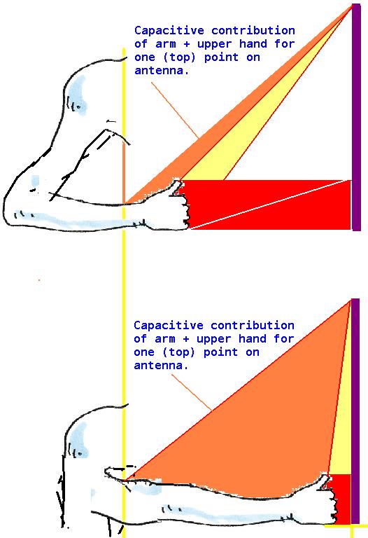
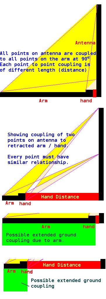
I strongly suspect that "underestimating mid and particularly near field capacitance " is due to angular coupling to the arm not being factored into the calculations - I am sure that this gives an additional capacitance "curve" which must be added - and it has maximum value closest to the antenna and drops to 0 when the arm is not extended.. I expect the curve will be something like a sine multiplied by inverse square of the distance.. or some similar geometric relationship based on arm and antenna length. I suspect that the deviation from the Glasgow sums will reduce as the antenna length is reduced. (as in, I suspect that length, and the lack of computing this WRT the arm, causes the error - and that if length is reduced such that coupling to the hand can only happen purely on the X axis, the hand alone will be "seen" and there will be no additional arm capacitance to screw things up.. but such an antenna would probably need a length of perhaps 11cm, need to be perhaps 5cm diameter, and be more like a plate sensor)
Back before your spreadsheet I used a simple spreadsheet I devised which based hand capacitance on simple capacitive plate sums - I took the antenna diameter as the width of one plate, gave the hand "plate" the same "width" multiplied by a "fiddle factor" (usually 1.5) and gave both "plates" a length of somewhere like 10cm.. I summed both areas, divided this sum by 2, and let each plate be equal to this area.. Then computed hand capacitance for these plates seperated by distance, and added an antenna "background" capacitance constant which I just guessed at or was based on measurement.
The above was, like the Glasgow calculations, obviously innacurate - but it was easier to alter the fiddle factors to get what one wanted to see ;-) LOL.
What I really want is something like the above but where I can compute angular capacitive components to account for the arm - because I believe this is likely to be highly significant.. The length of the antenna, for example, if one is only calculation hand capacitance "directly in line" has no influence (provided it is linger than the hand on the vertical axis) other than to increase background capacitance - and this is obviously absurd.. I believe that for a correctly modelled antenna, the length will prove to be highly significant for linearity.
I think (but have not proved this, although experiments incline me to thinking there is truth in it) that longer thinner antenna give better linearity than short fat ones. I also think (unproven) that an antenna having the length of the null distance might be optimum for linearity.
But, for now, the calculations (however derived) at least give a "ball park" against which simulations can be run - they are certainly better than nothing.. And your spreadsheets have saved me a lot of time... One needs to define aproximate component values in order to even start playing with prototypes, and these calculations are still better than guessing. I think the truth, when it comes to capacitive sensing of such tiny changes over such large distances, that one will never get perfect simulation - there are just too many complex variables.. It comes down, in the end, to hands on -
Even "hands on" one has problems actually verifying what one is seeing - the environment, the test methods, all sorts of things can make a big difference - As I keep discovering and forgetting! ;-(
The irritation is that I am sure, given the details in my next posting, a highly competent mathematician could derive a formula which could be put into spreadsheets and which would return far more accurate results for theremin application.
Fred.
I am going back to voltage outputting AFE - With this I get a voltage proportional (although distorted) to distance.. A bit of analogue shaping and I can get this quite close to "Actual" (not musical) linear.. So I get 0 to 10V for distance from antenna to "null" point... This becomes a CV at 1V/Octave, can reduce it to whatever I want, say 0 to 4V for 4 octave coverage..
To go up an octave (register switching) just add 1V - one has complete control over range and register... This voltage will drive VCO's and VCF's etc... And I am able to control any "normal" heterodyning theremin using voltage control.. One can tack as many VC modules or theremins onto this CV as you want, independently tune them if you want, and end up with chording / polyphony.. You can add voltages from sequencers and get patterns controlled by the master AFE... Or one can simply have one theremin module and a register switch and have a true analogue heterodyning theremin with register switching..
Its complex, but gets rid of all the headaches - splitting the control mechanism from the sound engine (as you are doing with your digital implementation). Lev's design was brilliant in its simplicity, but this is the 21st century - I am quite sure that if Lev was designing a theremin today he would not do it the way he did in the 1930's ! And that his 21st century design would use present day technology and be far superior to the RCA or Claramin.
Perhaps I have been missing the reality - been seduced by the retro electronics facination (the dark side? LOL ;-).. The old technology has a place due to its simplicity, but is probably better suited to mid-range or low cost starter instruments and toys.. Adapting this technology to create modern pro instruments is probably silly.
Looking at Bob Moogs advanced theremins (particularly the EtherVox) all the "simplicity" is gone! - the boards are packed with loads of analogue and CMOS, Big SMD MCU's, Eproms, transistor arrays, multipliers - they are highly complex modern instruments - With the EtherVox about the only "retro" components are the large air coils and some stuff at the front-end... The number of trimmers in the E-Vox is frightening! Setting up one of these would give any technician nightmares!
Fred.


