


I meant heinous in a good way! I wouldn't have suspected the part was so small!
Let's Design and Build a (mostly) Digital Theremin!
Posted: 6/14/2020 10:02:06 AM

Eric, I've been meaning to mention this, but I keep forgetting:
The new encoder board that I have in the works has a full bank of four encoders and will be a little bulkier than the four separate hard-wired boards that you now have. Basically it has to be larger to accommodate two 4x2 ribbon connectors that are placed horizontally on the vertically oriented board. The wide 16-wire left- and right-bank ribbon cables with the 8x2 connectors that mate with the MAIN FPGA board will each split into two narrower 8-wire cables with 4x2 connectors that plug as pairs into the left and right encoder boards. Having two smaller connectors on each encoder board makes the pcb layout narrower and less messy and also helps with lead dressing so that you aren't trying to put curves or folds in 16-conductor cables. Having those individual encoder boards hardwired to a ribbon cable as we had for the prototype is no good, and was only done because of my curved Pro front panel.
The new board is 0.9" wide, 4.16" long, with an encoder spacing of 1.1811" (30mm). I'm bringing this up now so that you can incorporate these dimensions/clearances into your experimental panel layouts. I'll send you a note and a link when the board is up (if it isn't already...).
Posted: 6/15/2020 4:18:07 PM
Encoder Speed Knobs!
I absolutely hate the shiny plated knobs on my D-Lev Pro (-totype), and all of this printing talk got me to thinking about why I hate them and what I could try as an alternative. They're currently too slick and too large to spin quickly. At the same time I've been playing with the goofy little encoder knob on the Prusa Mk3S printer and the logic behind it's design with the single flag pointer has started to become apparent.
With the 30mm spacing on the D-Lev there isn't room for the big flapper without interfering with an adjacent encoder. And encoder wheels with the finger dimple like you see on test gear are my favorite and don't look so dorky, but that dimple takes up space too.
I decided to print up a few types of knobs with little pins sticking out to allow you to lay your thumb flat on the knob and crank it to rotate. I've put two on my current theremin and despite the appearance I'm liking them a lot. I think the larger one is a little easier to spin precisely, but the smaller one lets you feel the detents better. It also makes pressing the encoder button more efficient, even though you don't have many button pushing calls remaining.
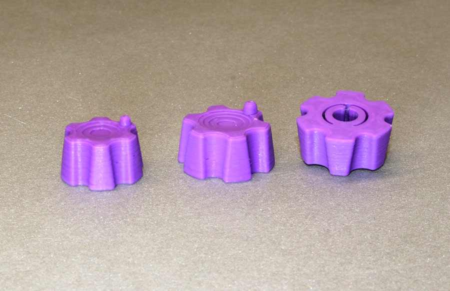
Anyway, I though you might want to print up a couple yourself to see how they work right next to each other. I'll send you a link for the .stl files, and I'll upload STEP files too in case you want to alter them. I guess my thinking here is if these are worth the effort I could machine one from metal, polish it up and make molds so that they could be cast in small batches. They would look prettier, although I would expect to still keep a printed insert for the part that grips the encoder shaft (too hard to cast that).
Oh, BTW these are for the slotted shafts - I don't remember if you have those or the flatted ones. They might still work for a test, or I can change them to work with flat pretty easily.
Posted: 6/16/2020 6:29:37 PM
"The new board is 0.9" wide, 4.16" long, with an encoder spacing of 1.1811" (30mm). I'm bringing this up now so that you can incorporate these dimensions/clearances into your experimental panel layouts. I'll send you a note and a link when the board is up (if it isn't already...)." - pitts8rh
Roger also sent me Eagle exports of those schematic and PWB layout files, which seem to open fine in KiCad (v5.1.6 converts and imports them, I'm running the Ubuntu build in Linux Mint). Being able to open and manipulate them is fantastic! I just uninstalled my trial version of Diptrace.
"I decided to print up a few types of knobs with little pins sticking out to allow you to lay your thumb flat on the knob and crank it to rotate. I've put two on my current theremin and despite the appearance I'm liking them a lot."
Lookin' sharp, Roger! I do recognize the PRUSA knob C-clamp inside. I printed yours up yesterday (as you know) and it worked well on my flatted shaft encoders. Nice tight fit on the shaft. Now I wish I'd bought purple PETG!
[EDIT] The black PETG arrived, did some first prints with it the other day:
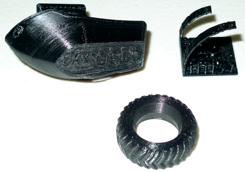
My first print was a "go for the gold" benchy boat. The bottom layer peeled off when I removed it from the table, and this was due to me not pre-heating things and also removing it from the bed before the mat was cool enough. The inside of the roof and general infill turned out quite hairy, and I mostly fixed this by slowing the feed down. Next I printed the tire from a Tesla truck toy, which came out quite nice. At upper right is a multi-test for printers and, except for some slight whisping between posts, it came out fine.
Posted: 6/17/2020 12:36:18 PM

You could use Shou Sugi Ban to make really cool theremin! It looks like a decent material for this cool instrument. My suggestion would be to contact these guys https://degmeda.eu/. I used this material for my fence, but maybe it could work out for theramin
Posted: 6/18/2020 3:41:11 AM
Communication (Knob) Breakdown
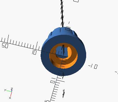
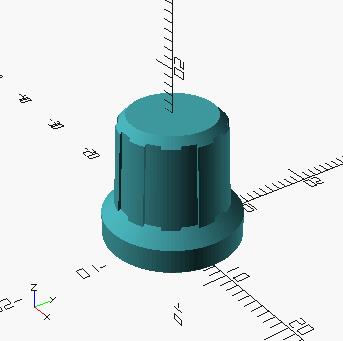
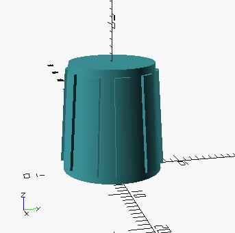
Spent the day modeling a communication type knob in SCAD and 3D printing:
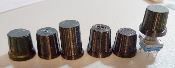
On the left is the knob I purchased and have been using on the D-Lev prototype. I really like these sorts of knobs, they're quite classy looking and feel good to operate. The most problematic issue with them is the setscrew, which is great and works well and all, but it invites ESD events. And there is the meaningless pointer. A knob seemed like a good way to learn more about SCAD, as well as PETG printing (and it got me out of working on presets) - so off we go.
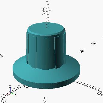
I went through many variations as seen from left to right, but finally settled on extremely similar dimensions to the original. A certain amount of engineering seems to have gone into this knob, they got just about everything ergonomically right IMO. Instead of the PRUSA / Roger C-clamp on the inside (which is actually very snug and positive feeling), I decided to try just a D type hole. Surprisingly, the Ender-3 can print to fairly close repeatable tolerance, and just making this rather snug seems sufficient to hold it on the encoder shaft. Here's a better view:
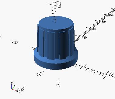
The outer knurls are 10 just slightly recessed regions - IMO all you need here is enough to get a grip with a light touch. Underneath, the D hole starts somewhat up from the base and opening of the hole so as to place the knob farther down on the shaft and hide more of it and the threaded mount.
All parameters are tweakable up-front in the SCAD text code file, which is handy. All sorts of knobs, with and without skirt (!), can be dialed up effortlessly and rendered to an *.stl file. In the Cura slicer I had some major issues with the concentric type layering, I don't know why it insists on starting in the center rather than at the edges, but doing so gives it almost no grip to get going on the first layer, hence the bunged up tops of some of the knobs in the photo. Switching to zig-zag fill solved that. Also, I was a bit obsessed at first with radius / chamfer on inside and outside corners (difficult to do in SCAD), but the printer nozzle diameter (for better or for worse) puts a "minkowski" round on everything in the XY plane (like rolling a small disk around the profile).
I need to try painting them to see if that improves their looks. As-is they aren't all that fantastic looking, though I'm not using the finest printing options either.
Much thanks to Roger for spearheading this activity! I don't think I would have attempted it on my own.
Posted: 6/18/2020 11:43:45 AM
"In the Cura slicer I had some major issues with the concentric type layering, I don't know why it insists on starting in the center rather than at the edges, but doing so gives it almost no grip to get going on the first layer, hence the bunged up tops of some of the knobs in the photo." -Dew
From the smooth appearance of the tops in your photos it looks like you are correctly printing these upside down. Is that right? If so, in Cura you can go under Experimental and set Bottom Pattern Initial Layer to Concentric. All of the other top/bottom layers should have the normal lines or zig-zag paths. On top of that, if/when you print on a textured plate the line pattern will virtually disappear anyway.
ON EDIT: After re-reading I see that you are printing upside down as I describe above, but it sounds like your problem is with bed adhesion when the concentric path starts in the center. I assume that your shells are printing first, but then it jumps to the center and spiral outward from there, and this is where you have the adhesion problem. Try increasing your Printing Temperature Initial Layer (under Material) to something higher; I sometimes use 250C (or even 260C with a texture plate) for the initial layer for PETG before reverting back to 240C or 235C for the rest of the layers. But this also tends to make the first layer flow out more and create an elephant's foot or mushroom head on your part. To help reduce this, go to Shell > Initial Layer Horizontal Expansion and set it to a negative number, like -0.3mm. This shrinks the first layer to compensate for the more fluid extrusion. But beware - PETG at higher temperatures can stick a little too well to the Build Tak. Prep the bed with hair spray or some stick glue before printing.
On the other hand if you are printing them upright and are trying to get by without supports, the top layer can be set to print concentrically too. Keep your normal top/bottom pattern set to lines or zig-zag Under Shell set Top Surface Skin Layers to 1 or more, and again go down to Experimental and set Top Surface Skin Pattern to Concentric. This will give the normal line pattern to bridge gaps but will finish with one or more layers of the weaker concentric pattern.
It looks like you are doing well with OpenSCAD. I tried to watch a video tutorial (because I don't understand the concept) but I fell asleep a few minutes into it, which is fairly common for just about anything now. I don't think it's for me - I just feel more at home with the drafting-type of parametric modelers.
If you want a knob that works on flats without set screws you might consider modifying the Prusa style to simply add a flat on the base side of the spring fingers, or alternatively just add a narrow web that stands between the open ends of the fingers but extends into where the flat of the shaft would go. I have some commercial molded knobs that are like this, where they don't really have a molded flat but instead have just one of six radial webs that is longer than the others to engage the flat. Also as another idea, maybe just the tiniest little bumps added to the inside of the ends of the fingers in the right locations would make the knobs work with both types of shafts, knurled or flatted.
A little Cura fuzz can greatly improve the appearance and functionality of knobs. Just enough to roughen the surface but still keep your flute features. And with that, a little light spattering of Rustoleum Texture paint or even some Krylon Matte clear can make these look almost indistinguishable from molded knobs.
Here we are printing knobs while the world is falling apart, which is probably the least important thing to be doing in the long list of things that we should be doing. But like you say, it's just fun! And for all the zillions of knobs out there, the D-Lev array of encoders can benefit from a specialized design, I think.
Posted: 6/19/2020 3:10:06 AM
"But this also tends to make the first layer flow out more and create an elephant's foot or mushroom head on your part. To help reduce this, go to Shell > Initial Layer Horizontal Expansion and set it to a negative number, like -0.3mm. This shrinks the first layer to compensate for the more fluid extrusion." - pitts8rh
Ah, thanks for that! I am experiencing elephant's foot on the initial layer and wasn't aware there was a setting for that (idiot me, it seems there's a setting for literally everything in Cura). As for the concentric pattern, starting in the middle is insane, and I've given up on it - zig-zag is working fine, and with a tiny bit of sanding you can't see the pattern.
"It looks like you are doing well with OpenSCAD. I tried to watch a video tutorial (because I don't understand the concept) but I fell asleep a few minutes into it, which is fairly common for just about anything now. I don't think it's for me - I just feel more at home with the drafting-type of parametric modelers."
It has it's issues, and I'm certainly still grappling with them, but in many ways it's simpler than any CAD program I've ever used, which IMO is more of a blessing than a curse (I'm OK at AutoCAD, but I loathe the interface and the games Autodesk plays) though it definitely could use a geometry processor and some more basic constructs under the hood.
"A little Cura fuzz can greatly improve the appearance and functionality of knobs. Just enough to roughen the surface but still keep your flute features."
Try as I might, I'm just not able to get the fuzz feature to improve anything I print, though it looks wizard on many of your parts!
"Here we are printing knobs while the world is falling apart, which is probably the least important thing to be doing in the long list of things that we should be doing. But like you say, it's just fun! And for all the zillions of knobs out there, the D-Lev array of encoders can benefit from a specialized design, I think."
And the world spins madly on. This seemingly lowly knob has been a great SCAD / 3D printing primer for me!
Two things I didn't mention in my last post re. the purchased communications knobs: 1) I have to tighten the set screw at a certain point, otherwise the knob will be either too high and look weird, or too low to operate the pushbutton mechanism. 2) The countersink on the bottom is too small to accommodate the encoder mounting nut, which places the knob higher than it needs to be, and exposes ugly (?) hardware.
After more iterations today, here's my latest knob SCAD: [LINK]. It's pretty basic, and maybe one way to see what's going on in SCAD in general? Inside SCAD, the Help | Cheat Sheet web link is pretty useful. This knob covers the mounting nut fairly well, and so sits lower than the purchased knob. The fit is tight too. Play with the params and get all sorts of knobs.
There's a total of ~5mm of thread on the encoder; 2mm of which is consumed by the nut, leaving 3mm for the thickness of the doghouse. I guess some sort of recess in the back is in order to give a shell thickness of 4 or 5mm elsewhere. Details & devils...
Posted: 6/19/2020 4:49:43 PM
D-Lev : The Knobbering
Printed a couple more knobs today and stuck them on the D-Lev:
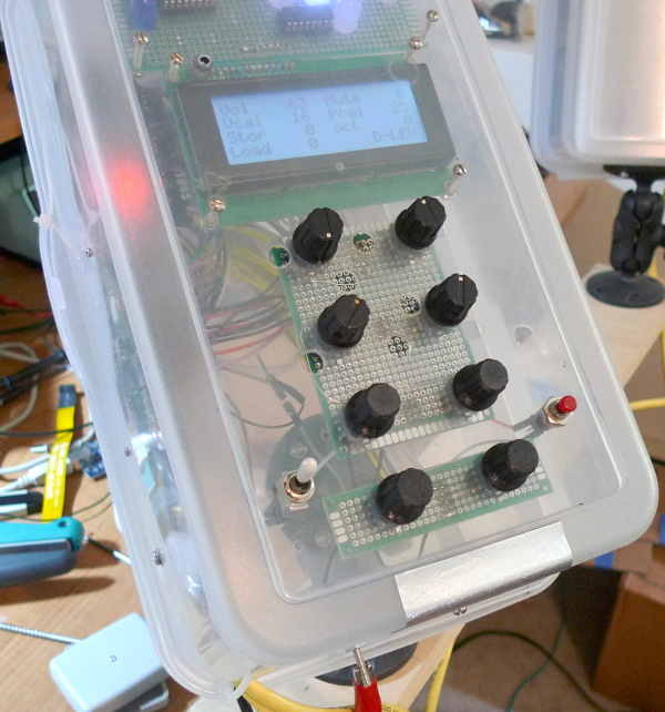
The lower 4 knobs are printed, the top 4 are store bought. Even without paint I think the printed ones are a little spiffier: they don't have pointless pointers, they do a better job of hiding the encoder mounting hardware, they all automatically sit at an even (and slightly lower) height, and they make an operational ESD event much less likely (no conduction via the setscrew because no setscrew). Roger's excellent advice of adding negative horizontal expansion on the first layer (-0.25mm seems to work well) has made the very top blend better, enhancing the 45 degree chamfer.
Here a sampling of the types of knobs you can get by manipulating the parameters in my SCAD file:
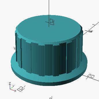
Fun - and useful - stuff!
You must be logged in to post a reply. Please log in or register for a new account.