"Yes, swapping the boxes may be best for traditional farther = louder playing. The DPLL parameters are the same for both so it should work. If you want to experiment along these lines I'd be interested in your results!" - Dewster
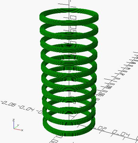
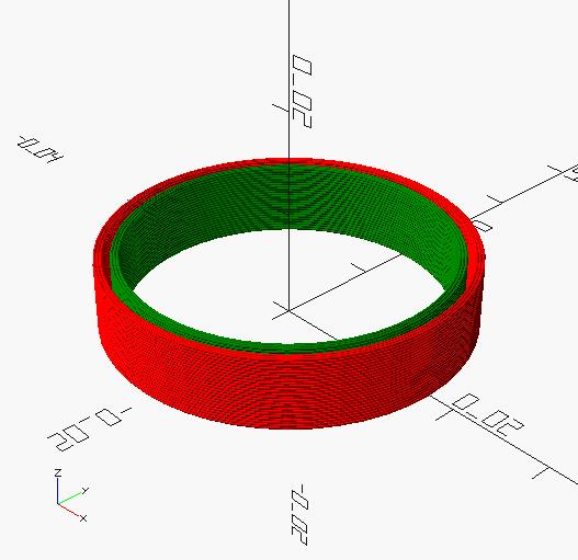
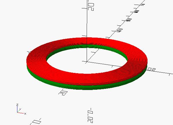
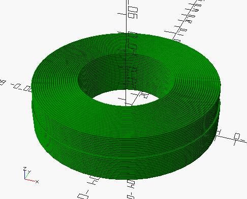
Thanks to the complete axial central symetry of my unit, it was not a great deal to turn my unit 180 degre and swap the plates. As expected having the great plate with the great coil (and small coil with the small plate) brings an additionnal separation of frequency (P/V is greater) which is good.
For sound checking, I used "swap P and V" = 3. If I check the logs, a cross point still exists (left hand flat on plate, right hand away) but no noise artefact in this area. And of course, nothing in the high pitch near octave 7.
"I just posted an improved version of the librarian: https://d-lev.com/support/d-lib_2024-02-16.zip
The initialization now samples at 1Hz which gives a better baseline, all readings go through the boxcar and LPF, the LPF is now single pole, HPF is also displayed, and you can pick which axes to log via the -p and -v flags (the default is both)." - Dewster
Sample rate = 1Hz, just for sake of filtering ? it still shows interval of 2s.
Maybe it worth adding space chars or a "|" to separate columns in some specific conditions (line 44 here) :
34 944764.3 679.4 -664.1-10333.9 24975.2111446.6 712238.9 -1827.8-448831.8-224951.6220927.8526149.1
36 944616.0 -526.9 -821.0 -9812.2 24388.7111446.6 711978.1 442.8-449033.6-237068.7220771.9526149.1
38 943947.2 -150.5 -1528.3 -9385.3 23826.0111446.6 719480.7 10494.7-443227.8-247745.1219885.6526149.1
40 941214.6 -6818.1 -4418.9 -9055.1 23286.7111446.6 776444.4 75751.2-399146.2-255845.4217442.2526149.1
42 938441.1 2670.7 -7352.5 -9008.7 22740.2111446.6 837316.2 47899.5-352040.3-260750.6213492.9526149.1
44 942821.9 3368.2 -2718.7 -8768.8 22257.7111446.6 961467.1195197.9-255965.9-262216.3208957.1526149.1
46 934698.1 -5811.2-11311.7 -8811.6 21782.3111446.6 1260615.5264078.0-24468.9-254273.4208172.1526149.1