Let's Design and Build a (mostly) Digital Theremin!

Posted: 11/25/2013 9:23:42 PM
Thierry

From: Colmar, France

Joined: 12/31/2007

Please allow me (as a non-anglosaxon, a non-engineer and a non-digital elucidated) a simple question...

Seen that you intend to do a digital processing of the RF signal, why do you worry about things like RF amplitude, hum or other RF straying into the pitch antenna? You could use FM receiver technology from the late sixties and send the dirty RF signal (a few uV will be enough) through a 5 or 6 stage limiter amplifier and either make directly use of the resulting square wave or send it still through a not too narrow LC filter to restore the sine wave at constant amplitude throughout the pitch range. There were even monolithic bipolar ICs for that if I remember well. 

Especially if you will do the linearization later on the digital side, you could get rid of the large inductance...

Or am I completely out of topic with this thought?

Posted: 11/25/2013 9:56:58 PM
FredM

From: Eastleigh, Hampshire, U.K. ................................... Fred Mundell. ................................... Electronics Engineer. (Primarily Analogue) .. CV Synths 1974-1980 .. Theremin developer 2007 to present .. soon to be Developing / Trading as WaveCrafter.com . ...................................

Joined: 12/7/2007

Thanks Dewster!

There are some nice books dealing with tube circuits - and the capacitance/magnetics book also has some useful old stuff!

Not sure whether to post this on the open.theremin thread, or here, or nowhere - LOL ;-) - But below is my (slightly) modified version of your "tankless" series resonant oscillator - some of the components selected were chosen for simulation (the 4069 is a model I constructed as a 'analogue' digital component - rather than using the 'digital' models that cause problems in my simulator - so I cannot be SURE its accurate).

This runs at about 268kHz with the H11F1 varying the frequency by about 10kHz - Antenna amplitude varies as the H11F1 varies from about 100V P-P to about 200V P-P (the H11F1 is simullated by a resistor from 100R to 200kR - R7 acts to limit this span and linearizes the curve) - C3 is not critical, but, as you say, its value does affect the antenna amplitude somewhat.. Anything between 100p and 2n works, but 1n5 seems optimal for this frequency.. Theres about 3.5kHz change in frequency for a 1pF change in antenna capacitance.

OTT ESD protection is shown - I use mini neon tubes (90V firing) as I have a box load and they were about 3p each! ;-)

I have found my H11F1 tuning method works well on other oscillators I have built (its great when used in applications requiring a VCO/CCO) *see notes in following posting - but the LED/FET are subject to temperature, so I would have a couple of SMD transistors mounted under the H11F1, both bonded to the H11F1.. One of these operating as a temperature sensor, the other as a heater.. Blob some polyurithane foam on top, and one has an oven..

(ESD stuff can be greatly simplified if peak antenna voltage never exceeds 90V - as then one only needs one neon between antenna and ground - I would probably choose this option - C2 would also then be safe as a single 22p 100V part.. The design above caters for peak antenna voltage up to 180V, and caters for ESD transients of many kVs)

Fred.

Posted: 11/25/2013 10:44:01 PM
dewster

From: Northern NJ, USA

Joined: 2/17/2012

"Especially if you will do the linearization later on the digital side, you could get rid of the large inductance..."  - Thierry

Interesting.  The large inductance is necessary to sense small capacitance changes, I'm not sure there is a way around that, though operating at higher frequencies could reduce the value. 

Constant amplitude isn't important for a Theremin that doesn't heterodyne, but changing amplitude likely indicates a non-ideal (other than 360 degree) phase path through the oscillator which likely lowers sensitivity.

Hum and other interferers can get in and cause erratic operation, so yes, some filtering here could do a lot of good.  But my circuitry doesn't use the signal itself directly, it uses the deviation from a center frequency, which is conveniently given by the DPLL loop filter accumulator.  This value is low pass filtered by the behavior of the PLL.  I've tried filtering it further with 1st and 2nd order digital filters but haven't seen much in the way of improvement, so it's probably just easier to set the PLL bandwidth to wherever the cutoff should be for quick response (1kHz or thereabouts) and use a 1st order digital LPF to improve resolution somewhat.

I've thought of lowering the LPF cutoff point the farther the hand gets from the antenna to increase SNR, something I intend to experiment around with.  The ear is much less sensitive to pitch bobble at low frequencies, so it isn't a huge deal, but it looks bad on the LED tuner display.

Posted: 11/25/2013 10:54:12 PM
dewster

From: Northern NJ, USA

Joined: 2/17/2012

Looking good Fred!  Very interesting tuning arrangement.

Have you tried simulating using a 10mH inductor in series with the antenna?  That should give you more sensitivity, and would restrict the highest voltages to just the antenna.

Posted: 11/26/2013 12:54:39 AM
FredM

From: Eastleigh, Hampshire, U.K. ................................... Fred Mundell. ................................... Electronics Engineer. (Primarily Analogue) .. CV Synths 1974-1980 .. Theremin developer 2007 to present .. soon to be Developing / Trading as WaveCrafter.com . ...................................

Joined: 12/7/2007


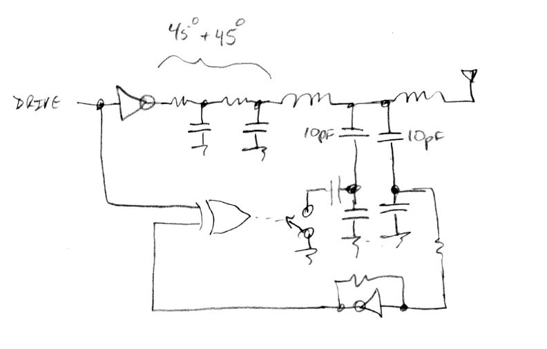
"Have you tried simulating using a 10mH inductor in series with the antenna?  That should give you more sensitivity, and would restrict the highest voltages to just the antenna." - Dewster

No, I havent - One of the big attractions to your oscillator was its simplicity (before you added the extra inductor, LOL ;-) - As soon as one gets to having two resonators, I fear rhat things start to get "peculiar" - the "peculiarity" can be useful for linearization or for moving the sensitive point to the antenna, or for amplification of sensitivity - But these all come with a high price tag.. One has two sets of resonators to calculate, and their actions on each other are far from simple.. I will probably stay with parallel LC tank with series LC antenna, or with the Lev topology, if I want to go this route  - at least I have some idea about how to get the best component selections for these..

80V P-P to 160V P-P is a big enough antenna amplitude to overcome problems I have had with low voltage antennas.

This oscillator is for a strange "new" topology I am devising.. I will be locking the antenna oscillator (osc A)  to a Xtal clock, using it in a PLL (which is why CV frequency control is needed) so that the antenna (and other antennas including volume antenna in a multi-antenna system,  or for multiple theremins all synced to the same clock - even a polyphonic theremin if such a thing was playable, which I doubt! ;-) will always be radiating a fixed constant frequency.. and as such, any antennas or synced theremins will not interfere with each other.

The error signal from the PLL will be a CV out which can be tailored / shaped / scaled to taste, and can drive a HF VCO (like the diagram above) to provide a variable output frequency proportional (or at least related - shape etc modified to correct linearity, range/span, register etc) to the players hand capacitance..

On a basic theremin, one would have a constant frequency variable oscillator "inside" A PLL connected to the antenna, and a voltage variable frequency 'reference' oscillator driven by the (modified) PLL error voltage.. So one ends up with two oscillations that can be heterodyned in the usual way.

Sensitivity is no real issue - I can amplify or attenuate the error CV as much as I want, so having user adjustable sensitivity (as in, a knob to set how many octaves are available in given 60cm) and likewise, linearity is no real issue - shaping the CV will allow user to adjust linearity to suit them.. I have played with this idea on some prototypes, but the new "upside down" topology looks like I can make it all a LOT simpler.

Its actually aspiring to be a wee bit more convoluted than the above, because I intend (eventually) to turn the error voltage into a voltage giving 1V/Octave change on the output and other HF oscillators behaving correctly in response to this CV..

But I will start with a simple theremin ;-) - or at least something theremin related - I think I may well leave "real" theremins to others - but the same circuits could be used in all.. May well just do a single board people can connect to whatever they want..

Fred.

ps .. I realise this is OT, as what I am talking about is all analogue, not digital - But the core AFE oscillator, even though I am not using it at all like you are, actually looks like quite an elegant way to implement an analogue theremin IF one has a means of correcting sensitivity and linearity..

I would have real problems doing these corrections on the RF side (just as there are real difficulties correcting for linearity and sensitivity on the RF side of all theremin front-ends) with your oscillator topology - it would mean going back to double resonator stuff..

But, I think the common ground between your approach and my latest escapade, is that with both, the front end performance (in terms of sensitivity and linearity) is not critical, as these can be corrected from the derived data.
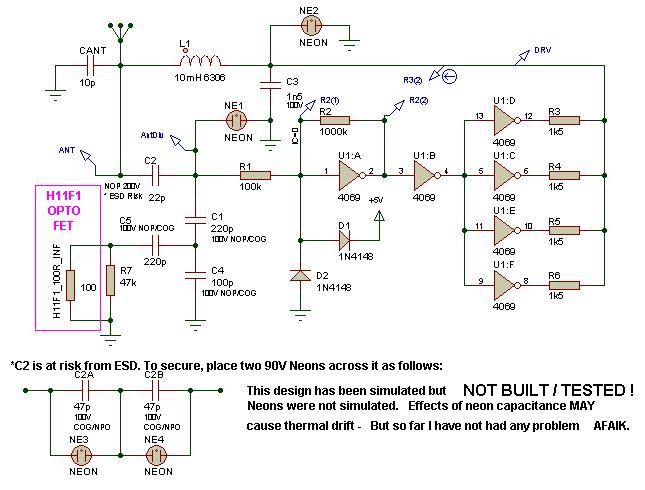
*Re: H11F1 tuning..

Suitable only for oscillators which can tolerate a capacitively coupled resistive load (and resulting loss of Q) at the antenna or a capacitance dependent frequency determining node, and where resulting (inevitable) variation of amplitude at this node (and if applicable, any related nodes) is acceptable. Beware that the voltage across the FET never exceeds its rating - I would not allow more than 20V across it, its rated at 30V.

I have used a portion of Dewsters capacitive divider and split the ground-side capacitor into 2 capacitors, (C1 and C4) to reduce the amplitude of the signal coupling via C5.. Capacitance seen 'by' the antenna is determined by series capacitance of C2-C1-C4 with an aditional series RC (C5-R7||FET) in parallel with C4 - It is the changing of the value of the R in this RC which facilitates tuning - at a price!

This scheme is probably not suitable for many usual theremin applications - it can be used on theremins with low antenna voltages by having only a series capacitor to the FET, but the incurred losses (reduction of an already low voltage) makes this an extremely poor option. When in its most significant operational mode (resistance lower than 50k, where tuning is most effective - or in the case of my circuit where a 47k is in parallel with it, resistance is limited to 47k- adding a parallel resistor helps to linearise the response of the FET) it effectively dissipates energy, so loading the antenna resistively (as in, the energy is lost, rather than recovered on the next 1/2 cycle).. this loading of the oscillator affects the amplitude and reduces effective Q - but for my applications I am often not particularly bothered by that..


http://www.fairchildsemi.com/ds/H1/H11F1M.pdf

I have also used reverse-biased opto transistors as varicaps, being controlled by the LED, but they are less predictable - althoug I have had some good results from dual isolators with their emitters connected together and using the collectors as capacitor terminals.. Unfortunately there is absolutely no data available for parts used in this way, and therefore no security regarding use of this in a product. If anyone knows of any dual transistor opto isolators which have base connections to both transistors, please advise me! - These would be a lot more useful!


Posted: 11/26/2013 4:04:56 AM
dewster

From: Northern NJ, USA

Joined: 2/17/2012

"One of the big attractions to your oscillator was its simplicity (before you added the extra inductor, LOL ;-) - As soon as one gets to having two resonators, I fear rhat things start to get "peculiar""  - FredM

I hear you.  But, compared to the complex parallel tank coupled to a series EQ, a series tank with series inductor (of roughly the same size as the tank inductor) is (famous last words) relatively benign.  You will of course get a reduction in resonant frequency, but you also get a noticable increase in sensitivity (and so SNR), a large boost in antenna voltage swing, and another LPF pole between your circuitry and the world.  Outside of the expense of the extra inductor, I haven't encountered any downsides to adding it (grain of salt).

Posted: 11/26/2013 4:16:17 AM
FredM

From: Eastleigh, Hampshire, U.K. ................................... Fred Mundell. ................................... Electronics Engineer. (Primarily Analogue) .. CV Synths 1974-1980 .. Theremin developer 2007 to present .. soon to be Developing / Trading as WaveCrafter.com . ...................................

Joined: 12/7/2007

"non-anglosaxon, a non-engineer and a non-digital" - Thierry

LOL ;-)

Dear Thierry -

We are all one!  All our concepts of "difference" are, IMO, delusory .. Even on a scientific level, the differences between even the most dissimilar humans is so minor as to be below any sensible noise baseline.. Educationally, I think that most of us here have our specialisms, and some of us are perhaps more lazy than others - but we are far more alike than different! (for one thing, we are all completely insane - we all have an interest in theremins! ;-)

Please forgive me if my abrasiveness has caused you to feel disliked or whatever - I am just a touchy non-mathematician who can be a bit stupid and egotistical, and who really cannot afford to lose any more friends.

I know your message was addressed to Dewster - My apology for once again butting in.. However I do feel I need to admit that I regret my recent "needlessly strong" response to your contributions... And to admit that next time I may well forget this feeling and act grufly again! - There are some people who dont mean to cause upset or conflict, but somehow always manage to.. I fear that I am one of these people - I get passionate about nonsense that really doesnt matter at all, and when passionate I am often completely blind to the feelings of others.. Or perhaps sometimes its even worse, and I actually get some stupid buzz out of trying to put a percieved "rival" down - particularly if I (rightly or wrongly) believe that they have done this to me.. Stupid and childish, but its a part of me I must own even though I hate it.

Fred.

Posted: 11/26/2013 5:05:10 AM
FredM

From: Eastleigh, Hampshire, U.K. ................................... Fred Mundell. ................................... Electronics Engineer. (Primarily Analogue) .. CV Synths 1974-1980 .. Theremin developer 2007 to present .. soon to be Developing / Trading as WaveCrafter.com . ...................................

Joined: 12/7/2007

"a series tank with series inductor (of roughly the same size as the tank inductor)" - Dewster

I will give it a try.. But, as I see it, theres a little more to it than that - The tank section will have (particularly with my VCO tuning scheme) a different varying load capacitance defining its resonance to the antenna resonator, and these two resonators will interact differently - I am particularly worried about this configuration within a Phase Locked loop, as depending on whether the antenna resonator is being seen as a capacitance or inductance by the tank, the behaviour of the correction (error) voltage could be wrong (for example,causing an increase in frequency when a decrease is required) and such a state would run away with no chance of recovering lock.

This is where my worry about "peculiarities" comes in - Some past experiment with linearization by dynamically adjusting the inductance of the antenna L have been spectacular failures - they work beautifully until something upsets the loop and it gets unstable - the nature of resonance, and the fact that it is possible to be operating on the 'wrong side' means that, in order to really get a working scheme, one needs to be checking the phase - Something your digital system does as a natural part of the operation, but its not intrinsic to my analogue stuff.

The analogue scheme which did work was where I had a filter (similar to that on the SC volume detector) generating a voltage proportional to the variable oscillator frequency, and used this to modify the frequency of the reference oscillator and therebye produce a linearizing function without an antenna resonator.. But I want a fixed frequency reference so that I can use this for volume! LOL ;-)

I think I spend a lot of time sabotaging my own designs, looking for flaws and creating "problems" just to avoid putting stuff to market - Some irrational and deeply hidden fear perhaps - I think a counsellor told me this about myself about 30 years ago! - said I was not as afraid of failure as I was of success, LOL ;-)

Fred.

ps .. There is another reason why I think a single inductor scheme may be better for me - its that the response curve (hand distance - frequency or distance to error voltage) has no complexity - I can design a voltage shaping circuit in the safe knowledge that regardless of variations in the inductance or capacitance of the parts fitted, I can DC tune the free-running frequency, and will get a known output deviation function (error voltage curve) - I can trim this to some predetermined range, and feed this to my EQ shaper - and then take this to a gain/attenuation stage to set required sensitivity before feeding it to the variable "reference" VCO..

Two inductors adds another variable - the tolerance of the 2nd inductor in combination with the antenna capacitance - if this modifies the response in any way which varies from build to build, then the shaping circuit will need to cater for this... I think...

Will play with some simulations - but the interaction of 2 resonators is a bu**er to simulate, so will probably only know for sure when I build the circuit - adding the antenna resonator is easily done on the breadboard.

UPDATE >> Have just run simulation adding another L and moving the antenna C to this, needed to change components at tuning section to maintain same control range - this increased loading and lowered voltage..

The antenna signal is higher (about 1.5* - would be more after better optimization) and sensitivity is now about 6kHz / pF (as opposed to 3.5kHz/pF).

Frequency analysis (not running the oscillator - driving network with swept sine) shows no real cause for worry - but there is a prominent peak at a few hundred kHz above the main one at 255kHz (oscillator operating frequency).. the roll-off is no better after this pole than without this 2nd inductor.. so im not sure about LPF advantages..

No verdict yet - wait for breadboard.. At this time I see no major advantage in the added inductor (in my application) except that I think it could allow the tuning to be more agressive and compensate for subsequent loss of amplitude, and the greater SNR is always a benefit.

Posted: 11/26/2013 3:26:58 PM
dewster

From: Northern NJ, USA

Joined: 2/17/2012

Very interesting Fred!

The LPF thing was speculation on my part, evidently not good speculation!

Not sure why I have a hard time thinking this way, but two inductors wired in series are obviously not coupled magnetically, but, like capacitors wired in parallel not sharing the same fields, they behave as one.  The tiny capacitance hanging off of the center of the two connected coils acts probably more like a coil tap than anything else (though it is of course resonant).  This is what got me thinking about tankless designs.  Why not tap the coil closer to the drive to reduce the amplitude and loading of the sense point (rather than knocking it down with a capacitive divider) and have this single tapped EQ coil do all the resonant work rather than two? 

This arrangement seems to works better if the sense coil is a separate coil rather than a tap, because the drive is then not blasting it directly.  And it is more sensitive to drive waveform - you pretty much have to feed it a reduced harmonic drive, like a triangle wave or sine wave, so as to keep the sense waveform smooth.  Some resistive loading of the sense coil seems to help smooth it out as well.  I need to experiment more with sense coil turns and location (currently looking at multi-level and MASH DAC topologies for the audio output).

Using a fixed frequency to feed all antennas and then tuning the LC to this is quite clean and innovative!  This is pure phase locking, as the design is already and always will be frequency locked.  I wonder if you could use high speed PCM driving an analog switch in series with the tuning capacitor rather than the FET?  Kind of a switched capacitor filter thing.

Posted: 11/26/2013 6:32:09 PM
dewster

From: Northern NJ, USA

Joined: 2/17/2012

Actually, if you use an analog switch instead of the FET, you might be able to make a bang-bang phase detector from an XOR gate, which would make the switch toggle at twice the clock rate.  Something like this:

The delay RC here is split into two 45 degree networks which may work better.  The resonant tap is split in two to maybe limit immediate feedback from mucking things up.  I also haven't paid any attention to the XOR logic, it may need inversion on the output or one of the inputs, etc. 

Probably wouldn't work - I think a lot of it depends on how much of a "flywheel" effect you get from the LC resonance.  Being a first order loop I believe it would have error proportional to the operating point.

You must be logged in to post a reply. Please log in or register for a new account.