


Wow Evan, that Colorlight i5 is quite the deal! But to use it easily seems to require a board on a board, which then would go on a 3rd board in the D-Lev (turtles boards all the way down). I would worry about the reliability of all of those connectors. If continuing in the FPGA direction, Lattice is looking better and better.
Let's Design and Build a (mostly) Digital Theremin!
Posted: 5/12/2023 12:12:41 PM
Posted: 5/12/2023 12:28:26 PM
Who Are You Going To Believe?
One thing I didn't really anticipate when using a relaxed pitch field + tuner was the impact of the loss of typically "Theremin" type pitch cues. Things like glissing for large pitch changes, pitch fishing, and small wavering around what the player intends to be a steady pitch are suppressed to the point where some listeners interesting misinterpret my (rarely) non-pitch corrected playing as being pitch corrected. And some players get the sense that pitch correction is happening where none is applied. Our sense of our own personal senses is often baffling, can't trust anything it seems (lying eyes, etc.).
Posted: 5/13/2023 2:46:18 PM
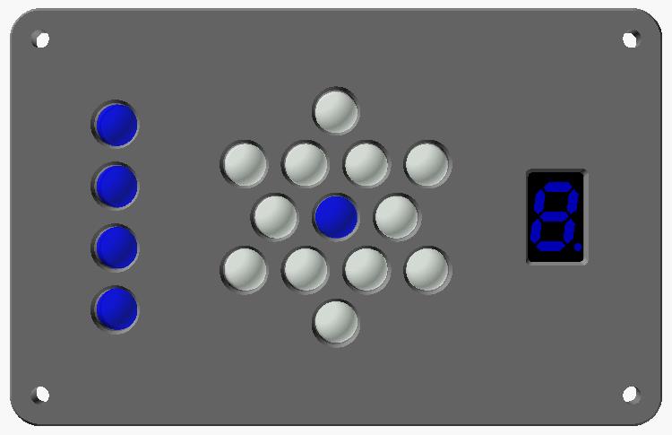
Mood Board
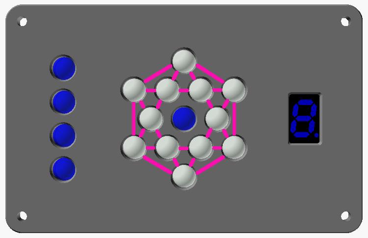
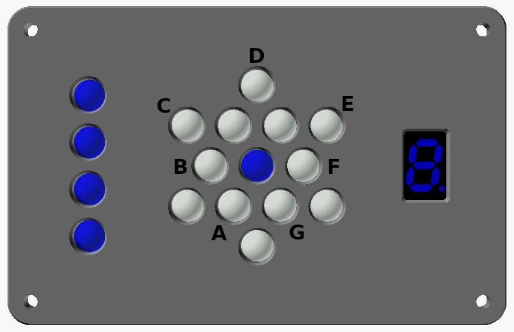
Long ago a product designer kindly sent me some of his mood board concepts. One of the prettier ones centered up the note circle. This morning I made this optional in the OpenSCAD file and exported some pix. The second pic has lines between the whole and half steps, which I suppose could benefit noobs, but there isn't exactly a ton of space to draw the half steps in. The last pic is what a lot of folks end up doing with a sharpie or similar - I've use the tuner for so long I don't feel the need for note names. And, for as asymmetrical as it is compared to this, I somewhat prefer the note circle on the right as it puts it closer to the pitch plate, where I really need it for interactive playing reference.
Posted: 5/15/2023 1:04:24 PM
Dongle Wars: The Prolific Menace
So I was upstairs the other day, setting up to make a short D-Lev kit video. I noticed that the kit #0 software was rather old and needed updating, so I plugged the kit USB serial dongle into it our Windows 10 laptop, download the latest command line librarian from the support page, unzipped it to a directory on the desktop, and opened a terminal window there, naively anticipating an uneventful minute or so of EEPROM pumping.
The view -k command returned a strange error message that I’d never seen before: "A device which does not exist was specified." So I opened the Windows Device Manager to check to see if there were any driver issues, only to find this waiting for me:
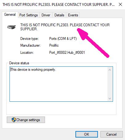
I should have noted or screen grabbed the driver version, it was dated 2022 something. “This device is working properly” LOL.
A brief web search suggested rolling back the driver, but there were no other versions in the driver list to pick. Another hour or so of web searching (this modern world) indicated a much older (2008!) driver v3.3.2.102 was the ticket, but of course Prolific has suppressed copies of that floating around too. This also seemed to be associated with a “Code 10” issue, wherein Prolific in their wisdom decided to just drop support for some of their older chips that were being pirated, leaving even legit chip users high and dry. One site recommended a program which would remove any new borked drivers, install the old working driver, and prevent Windows from ever updating it. The installer is on this fascinating drag racing site, it’s free with the option to donate:
https://www.ifamilysoftware.com/Prolific_PL-2303_Code_10_Fix.html
I downloaded, installed, and ran it, following the directions on that page closely. After a reboot the Device Manager nastygram was gone and the librarian was working once again.
Prolific, never again.
Posted: 5/19/2023 11:19:10 AM

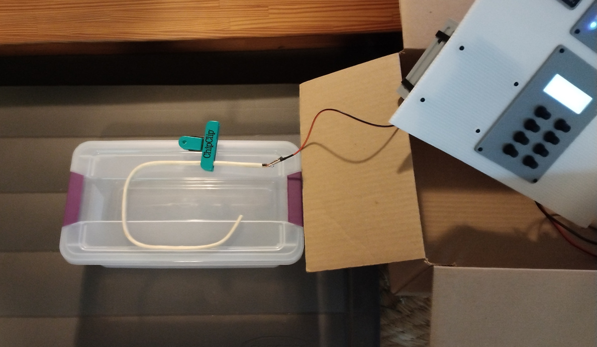
Sipeed Tang Nano 20K FPGA board with 8MB SDRAM is now available on aliexpress for ~ $25
Cross-posting from my thread
A lot of pins shared with on-board connectors and devices. Need to figure out how many pins can be used for theremin.
Posted: 5/19/2023 12:11:27 PM
Thanks Vadim! I wish they weren't so intent on making these things so microscopic, could probably have gobs more undedicated I/O. I'm thinking Lattice is maybe the way forward, they seem to have fairly reasonable prices and availability, and the toolsets are much more mature.
Posted: 5/19/2023 1:20:23 PM
Thanks Vadim! I wish they weren't so intent on making these things so microscopic, could probably have gobs more undedicated I/O. I'm thinking Lattice is maybe the way forward, they seem to have fairly reasonable prices and availability, and the toolsets are much more mature.
Then, the only suitable alternative I see is ICESugar Pro (or Colorful i9 with 45K LUTs, but it's more expensive and less open).
If you can solder SO-DIMM socket, looks like good replacement for altera core boards.
Posted: 5/22/2023 3:24:57 PM
"If you can solder SO-DIMM socket, looks like good replacement for altera core boards." - Buggins
It might be possible to get a Lattice part soldered directly, and avoid all the board-on-board action? I worry about long-term connectivity when it comes to connectors, probably 90% of electrical failures are mechanical in nature.
Posted: 5/22/2023 3:40:17 PM
Rod vs. Loop - Intrinsic C
I've been wondering how a pitch rod might compare to a volume rod in terms of intrinsic C. Obviously a loop, being more concentrated physically in one spot, has the potential to interact with the hand more, which should give higher mutual C and therefore higher sensitivity, but what about the quiescent operating points of the oscillators? We don't want them to ever get too close in frequency, otherwise they could very well interfere with each other.
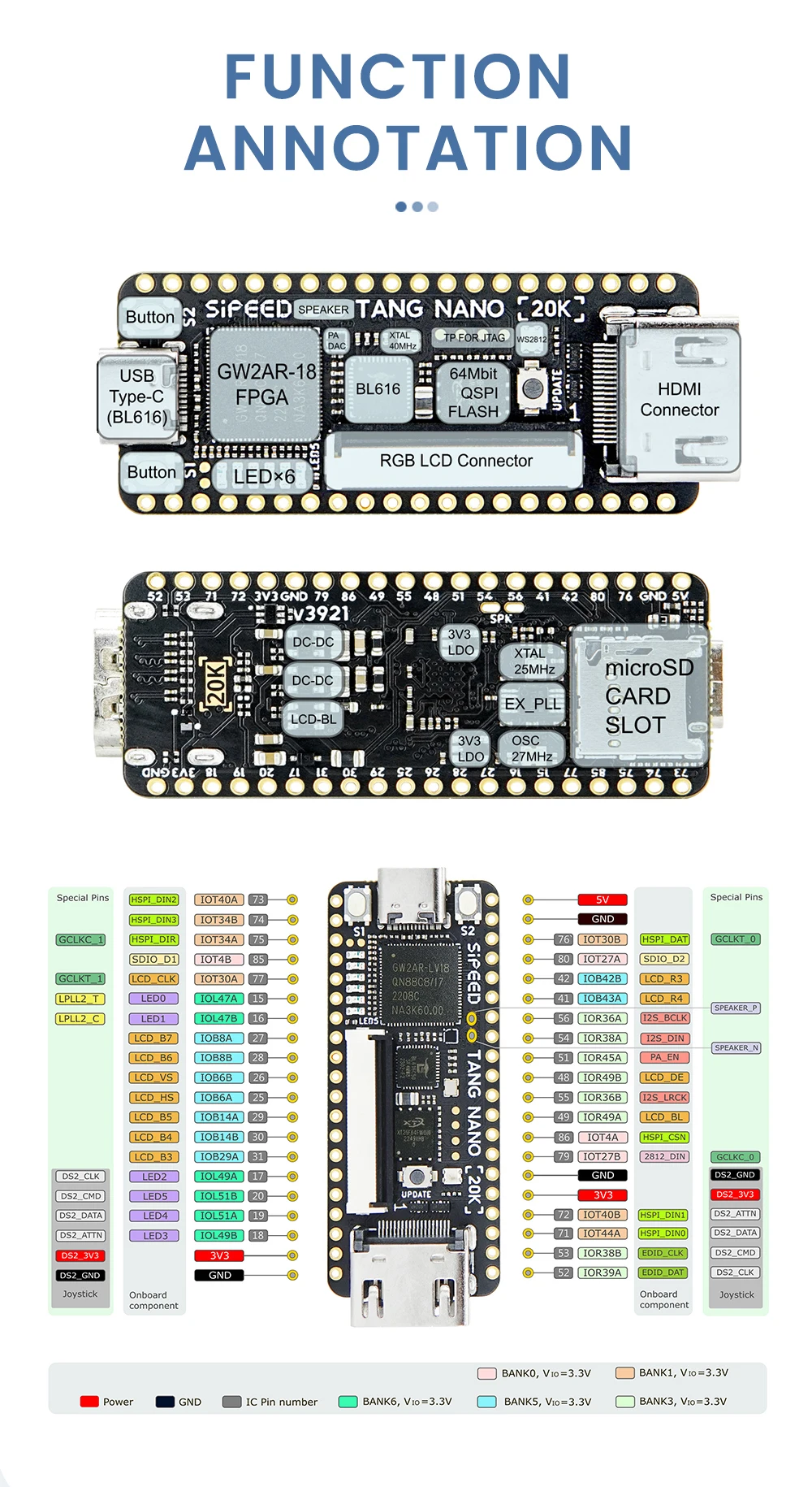
For this test I fashioned two antennas, each formed from 0.5 meters of 12/2 house wiring with all 3 conductors soldered together at the base. The volume coil of D-Lev kit #0 was used with PV[3] to obtain the capacitance values by peeking at the filtered pitch DPLL value via the librarian software. Intrinsic C = total - stray. A plastic PETG box was used as support, along with a plastic "chip clip". The whole thing is sitting on a small empty plastic storage tub, on top of a large mostly empty plastic storage container.
Above: The straight antenna positioned vertically, 4.91pF.
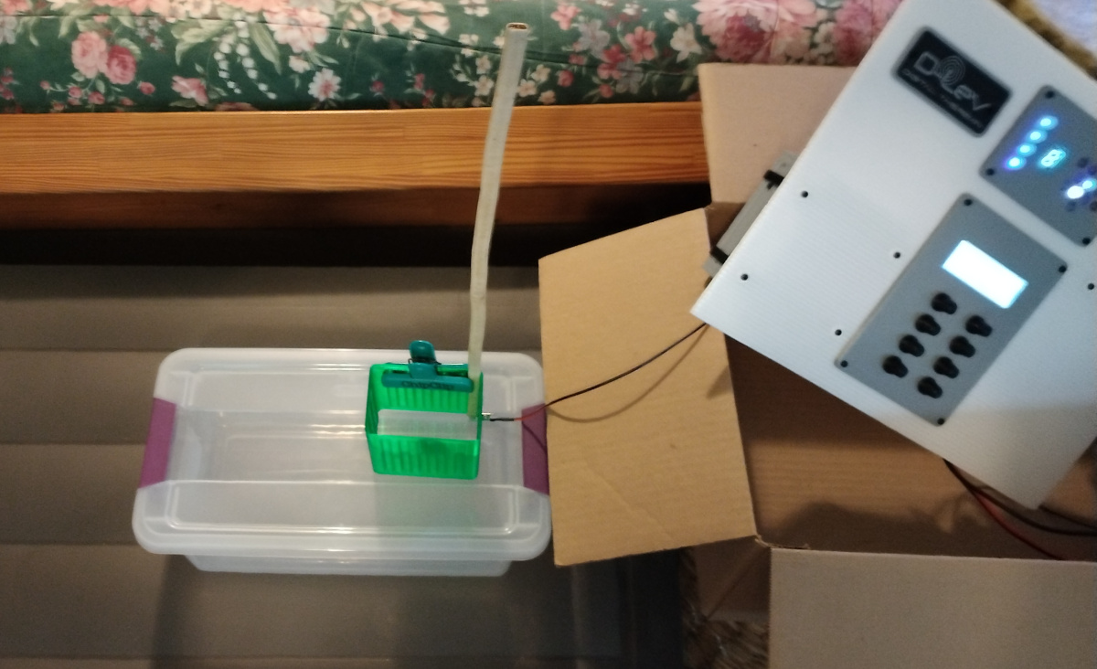
Above: The straight antenna positioned horizontally, 5.42pF.
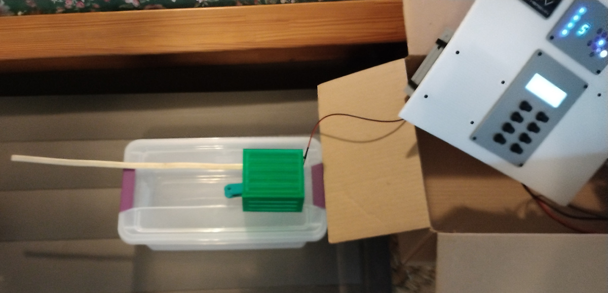
Above: The loop antenna positioned horizontally, 4.87pF.
This particular antenna gained 0.5pF when laid down, and then lost it when curled up. So it seems equal high aspect ratio conductors of equal lengths will yield roughly equal intrinsic C when configured and positioned as Theremin pitch and volume antennas, all else being equal.
This is yet another experiment I should have performed years ago, though mainly for others. The kit makes the test effort fairly minimal, which is nice. It amazes me how little basic information like this is out there.
Posted: 5/22/2023 7:33:58 PM

Complicating the conclusions of this test:
1) Vertical wire is surrounded mostly by air
2) The second picture has half the conductor lying on thin dielectric, Er probably ~ 2 something, and one-storage-box-unit height above another presumed dielectric. At this level of measurement I wouldn't ignore either of those, as they would add slightly to the effective measured C.
3) With the loop, all the wire is lying on the dielectric, further increasing the measured C. Let the loop hang vertically in space roughly like the wire in the first picture is oriented if you want to compare #1 and #3.
and
4) Two small-diameter conductors (small diameter relative to their spacing) will each be less influenced by their neighbor than if larger diameter conductors are used. Consequently the volume loop of picture 3 will electrically look more like a straight wire lying completely over plastic with very little loop effect caused by the folded back section influencing the other side. Larger diameter conductors or a tighter loop should begin to show more of the capacitance-decreasing effect due adjacent common-mode E-fields that I was describing in our email.
Now let's see if this works when I hit the Post button after all this time...
You must be logged in to post a reply. Please log in or register for a new account.