"When you say "equalizer" or "EQ" I assume you mean the linearizing coil?" - Dewster
Yes - I am talking about the linearizing coil, or more generally about the series LC circuit which loads the variable oscillator.
"But wouldn't the tank resonance point (as well as the fixed reference oscillator) have to change too in order to preserve linearity?" - Dewster
If one tunes the EQ and tank such that, at the null point, the EQ is extremely close to resonance, and the oscillators tank is tuned to be at this frequency - One now has the oscillator / EQ tuned for maximum linearity.
One then tunes the reference oscillator to this frequency.. And both the tank and reference tunings are 'sealed' - no change to these!
Now, the aim is to keep the EQ tuned ALWAYS to this resonant frequency when the hand is at the null position.. It is the EQ loading on the oscillator which is the primary influence, and to maintain linearity, one wants this loading to occur at the null point - wherever this null point is placed, and regardless of changes to "background" capacitive influences.
{Brown text refers to "normal" theremins - Blue text is more specific to my linearization scheme.}
If we look at a "normal" design, you will see that changes to "background" capacitance will change the resonant frequency of the EQ.. This can shift the (resonant) frequency up or down - For this reason, tuning of the EQ cannot be set to the optimum point - one needs to leave enough "headroom" to cater for normal variation in "background" capacitance... This is not a "real" problem - tuning of EQ/Tank in "normal" theremins is quite crude, and the curve (provided by the EQ) will give adequate linearization even when the oscillator is not tuned to the "optimum" (peak) point when at "null"... It will give adequate operation, but not optimum operation.
Changes in "background" capacitance will change the "section" of the EQ resonant curve over which the linearization operates, and the oscillator frequency will be shifted in proportion to these changes. Normal theremins effectively change (adjust) for these shifts by changing the reference oscillator frequency, so as to shift the null point.
I need to say a little bit about the "null" point - With "normal" theremins this point is arbitrary - it is simply the point at which the reference and variable oscillator frequencies are the same... And with well set-up theremins, this frequency will be close to the EQ resonant frequency.
With my design, the "null" point is "absolute" - It is the resonant frequency of the EQ circuit, and the oscillator is tuned to provide this frequency, and the reference oscillator is set to this frequency, at the "null" point.. One changes the position of the "null" point by changing the inductance in the EQ circuit, so as to bring its resonant frequency (and therebye bring the variable oscillator frequency) to the same frequency as the reference oscillator.
The EQ frequency is always the same at the null point (unlike normal theremins where it is determined by background capacitance) so the variable oscillator frequency is always the same (does not need retuning) and the reference oscillator is fixed.
With the above, equalization remains constant regardless of static changes to background capacitance, and hand capacitance always acts over the same section of the curve, and the best (sharpest) section of the curve (close to EQ resonant frequency) can be exploited.
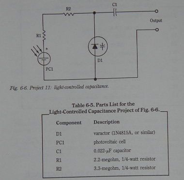
It is controllable variable inductance which makes the above really workable - One can perform the same effect using variable capacitance ( The only other theremin I have seen which is tuned at the EQ circuit is the Moog Ether-Vox, and this uses a complex linearizing circuit [tapped inductor] with variable capacitor for tuning ) - But high quality variable capacitors are not easy to come bye, and do not lend themselves well to automation.
Fred.


