coil tuning

Posted: 6/15/2012 2:17:14 AM
invisiblejelly

Joined: 3/18/2012

Hello now there seems to be only two options when constructing a theremin in reguards to coils..either one uses those small coils with the ferrite tuning thing in them or one winds one's own coils and one uses variable capacitors.There may be a third option that is by magnetically tuning the coil thus allowing fixed capacitors with a hand wound coil. 

http://www.crystalradio.net/crystalplans/coolplans/Magnetically%20Tuned%20Crystal%20Set/magtuned.jpg

the above is a crystal set with fixed capacitor that is tuned by using a horse shoe magnet in proximity to the coil.


Posted: 6/15/2012 3:27:18 AM
FredM

From: Eastleigh, Hampshire, U.K. ................................... Fred Mundell. ................................... Electronics Engineer. (Primarily Analogue) .. CV Synths 1974-1980 .. Theremin developer 2007 to present .. soon to be Developing / Trading as WaveCrafter.com . ...................................

Joined: 12/7/2007

Hi invisiblejelly

Yes, magnetic tuning does work - but I dont think it is practical for theremin tuning due to the variations one gets for tiny changes - remember, as things warm up they expand, and the proximity changes - not to mention problems with mechanical issues.

My original H1 theremins had a problem because they were mounted quite close to a loudspeaker - I discovered that, even though these speakers were advertised as "shielded", the leaking feilds upset my tuning - but this got me thinking about the whole issue:

You say: "there seems to be only two options when constructing a theremin in reguards to coils..either one uses those small coils with the ferrite tuning thing in them or one winds one's own coils and one uses variable capacitors"

There are, in fact, several more options:

A coil wound on a ferrite former can be 'tuned' (have its inductance changed) by passing a DC current through it - Many oscillator designs have DC currents passing through the coil anyway (The EW oscillator waveform centres at 12V so there is a "DC component" in this) - One can design the circuit to have adjustable biasing and thereby perform tuning.

The other method is to use the "saturable reactor" principle - this is a transformer where one passes a dc current through one winding, and the inductance of the other winding changes.. The principle is much the same as your "magtuned" circuit, except that you have DC control.

This saturable reactor method works well - I employ it in one of my designs. The key thing to remember though is that it is a transformer, so oscillator signals pass to the control winding - One overcomes this by placing fixed inductors either side of the control winding to block the oscillator signal. It is best to wind your own saturable reactors (or get them made) - but some common-mode chokes can be used - You can even use a IFT (one without in-built capacitor) - screw the slug right down, put the current between pins 1 and 3, and (for the 42IF106) you can vary the inductance from pins 4-5 from about 9uH to about 27uH.

One generally wants the control winding to have many more turns than the oscillator winding, as you want to change the core saturation with minimum current - one problem is that if one is not careful, the control winding will get warm, and this causes drift.

Then of course there are varicap diodes (all reverse biased diodes can be used as variable capacitances simply by changing the reverse DC voltage across them).

Fred.

Posted: 6/15/2012 3:28:30 AM
dewster

From: Northern NJ, USA

Joined: 2/17/2012

I think the key phrase here is "Without the influence of the magnet, the value of C1 will set the receiver to its lowest tuned frequency."  So I suppose this is tuning via core saturation.  I'm not an inductor expert, but wouldn't that lower the Q factor?

Oops, Fred beat me to it.  You go Fred!

"Many oscillator designs have DC currents passing through the coil anyway (The EW oscillator waveform centres at 12V so there is a "DC component" in this" - FredM

Theremin inductor selection and overall stability seems to be problematic enough without biasing oscillator transistors through the coils, no?  If I were designing an analog Theremin, I'd try to pick a design that didn't do this.  I think you can still get substantial drift from the currents induced by the large voltage swings through the "linearizing" coil, correct?  I think I see this in my AFE (it takes several seconds to "warm up") but I haven't measured it with a thermistor or anything yet.

Posted: 6/15/2012 4:10:20 AM
FredM

From: Eastleigh, Hampshire, U.K. ................................... Fred Mundell. ................................... Electronics Engineer. (Primarily Analogue) .. CV Synths 1974-1980 .. Theremin developer 2007 to present .. soon to be Developing / Trading as WaveCrafter.com . ...................................

Joined: 12/7/2007

"Theremin inductor selection and overall stability seems to be problematic enough without biasing oscillator transistors through the coils, no?" - Dewster

I am deeply undecided about this question - I certainly think it is true for the equalizing coil/s, but am inclined to think that the oscillator is less critical than I had thought before. I have built oscillators where I deliberately centred the waveform so that there was no DC component through the inductor, and never found any improvement in stability - and I have built oscillators where I deliberately varied the DC component and therebye performed tuning, and found no problem with stability.

I dont like the idea of passing DC current through the inductor, so dont do it - but my reasons are more to do with the fact that I always design with a view to production - And the whole basis of DC control depends on the ferrite charactaristics - And I cannot obtain the kind of technical data which gives me the assurance I need that these charactaristics are consistant... The only way I will use staurable reactors is when I design the transformer myself and get it made.. But have been badly let down doing this.. Got a couple of perfect samples from China, ordered production quantity, these arrived and bore no resemblence to my samples.

Tiny changes in the linearizing coil will have much bigger effect IMO - But I am not sure that there could be any problem with DC currents through this coil - Perhaps at turn-on (for a few microseconds) while the antenna is being 'charged'  - but once this has occurred, the antenna capacitance will be constant (except for hand capacitance) and no "DC" current will flow.

I suspect that the drift you are seeing may be more due to the active circuits / power supply / decoupling capacitors and semiconductor warm-up than due to the inductors.

Fred 

>> Added:

In all my experiments / circuits, I use extremely stable (band-gap) power supplies.. "biasing oscillator transistors through the coils" current is going to be dependent on the supply voltage - therefore any variation in supply voltage (due to temperature or whatever) would change any DC offset current through the inductor, resulting in drift.

Posted: 6/15/2012 2:01:56 PM
dewster

From: Northern NJ, USA

Joined: 2/17/2012

"And I cannot obtain the kind of technical data which gives me the assurance I need that these charactaristics are consistant..." - FredM

Yes, tuning via saturation strikes me as being overly reliant on on ill-specified parameters (like BJT beta).

"Tiny changes in the linearizing coil will have much bigger effect IMO - But I am not sure that there could be any problem with DC currents through this coil - Perhaps at turn-on (for a few microseconds) while the antenna is being 'charged'  - but once this has occurred, the antenna capacitance will be constant (except for hand capacitance) and no "DC" current will flow."

I guess I was talking more about the amplitude of the AC voltage swing through the linearizing coil, not any DC per se.

"I suspect that the drift you are seeing may be more due to the active circuits / power supply / decoupling capacitors and semiconductor warm-up than due to the inductors."

I suspect you're right.  The AFE relies on the CMOS threshold voltage to center and clip the LC sinewave.  (Uh-oh, talk about design based on on ill-specified parameters!)  Surprisingly, logic thresholds seem to be fairly steady things (famous last words).

Posted: 6/16/2012 5:00:36 AM
FredM

From: Eastleigh, Hampshire, U.K. ................................... Fred Mundell. ................................... Electronics Engineer. (Primarily Analogue) .. CV Synths 1974-1980 .. Theremin developer 2007 to present .. soon to be Developing / Trading as WaveCrafter.com . ...................................

Joined: 12/7/2007

"Yes, tuning via saturation strikes me as being overly reliant on on ill-specified parameters (like BJT beta)" - Dewster

Using a saturable transformer with a seperate winding for DC current (to control the saturation) one can simply use a variable current sink (op-amp + BJT with emitter feedback, ie voltage follower, dumping current into fixed value resistor, and getting this current through the collector which is connected to the control winding) one can get precise control of saturation current.

The above works well - My "problem" is that I cannot get data relating to the ferrites in the transformer - Even when I specify the application and got samples made to my specifications, there was huge variation between samples and production. One can buy 'reactors' but they are mostly for power circuits, and they are all too expensive... But I have found a few suppliers now who will make me some samples of what I want..

The reason I want to use this method is mainly for my voltage controlled heterodyning oscillators - the object is to have a VC front end, and implement a truly analogue register switching theremin..

But I also think there is a big application for these reactors in general theremins - The best place to perform tuning is by changing the equalizer resonance.. Having a fixed reference oscillator and variable EQ inductance keeps the theremin tuned for optimum linearity. The worst tuning method (and most common) is changing the reference oscillator frequency.

Reactors with several mH of DC controlled adjustment are quite possible - and this also opens the possibility of having a MCU automatically calibrate for optimum linearity - push a button, put your hand where you want the null point, and the control current is adjusted to set this null position whith optimum linearity regardless of the background capacitances etc.

Fred

Posted: 6/16/2012 10:19:14 PM
dewster

From: Northern NJ, USA

Joined: 2/17/2012

"The best place to perform tuning is by changing the equalizer resonance." --FredM

Sounds challenging!  When you say "equalizer" or "EQ" I assume you mean the linearizing coil?  Interesting way to tune a Theremin.  But wouldn't the tank resonance point (as well as the fixed reference oscillator) have to change too in order to preserve linearity?

Posted: 6/17/2012 2:05:06 AM
FredM

From: Eastleigh, Hampshire, U.K. ................................... Fred Mundell. ................................... Electronics Engineer. (Primarily Analogue) .. CV Synths 1974-1980 .. Theremin developer 2007 to present .. soon to be Developing / Trading as WaveCrafter.com . ...................................

Joined: 12/7/2007

"When you say "equalizer" or "EQ" I assume you mean the linearizing coil?" - Dewster

Yes - I am talking about the linearizing coil, or more generally about the series LC circuit which loads the variable oscillator.

"But wouldn't the tank resonance point (as well as the fixed reference oscillator) have to change too in order to preserve linearity?" - Dewster

If one tunes the EQ and tank such that, at the null point, the EQ is extremely close to resonance, and the oscillators tank is tuned to be at this frequency - One now has the oscillator / EQ tuned for maximum linearity.

One then tunes the reference oscillator to this frequency.. And both the tank and reference tunings are 'sealed' - no change to these!

Now, the aim is to keep the EQ tuned ALWAYS to this resonant frequency when the hand is at the null position.. It is the EQ loading on the oscillator which is the primary influence, and to maintain linearity, one wants this loading to occur at the null point - wherever this null point is placed, and regardless of changes to "background" capacitive influences.

{Brown text refers to "normal" theremins - Blue text is more specific to my linearization scheme.}

If we look at a "normal" design, you will see that changes to "background" capacitance will change the resonant frequency of the EQ.. This can shift the (resonant) frequency up or down - For this reason, tuning of the EQ cannot be set to the optimum point - one needs to leave enough "headroom" to cater for normal variation in "background" capacitance... This is not a "real" problem - tuning of EQ/Tank in "normal" theremins is quite crude, and the curve (provided by the EQ) will give adequate linearization even when the oscillator is not tuned to the "optimum" (peak) point when at "null"... It will give adequate operation, but not optimum operation.

Changes in "background" capacitance will change the "section" of the EQ resonant curve over which the linearization operates, and the oscillator frequency will be shifted in proportion to these changes. Normal theremins effectively change (adjust) for these shifts by changing the reference oscillator frequency, so as to shift the null point.

I need to say a little bit about the "null" point - With "normal" theremins this point is arbitrary - it is simply the point at which the reference and variable oscillator frequencies are the same... And with well set-up theremins, this frequency will be close to the EQ resonant frequency. 

With my design, the "null" point is "absolute" - It is the resonant frequency of the EQ circuit, and the oscillator is tuned to provide this frequency, and the reference oscillator is set to this frequency, at the "null" point.. One changes the position of the "null" point by changing the inductance in the EQ circuit, so as to bring its resonant frequency (and therebye bring the variable oscillator frequency) to the same frequency as the reference oscillator.

The EQ frequency is always the same at the null point (unlike normal theremins where it is determined by background capacitance) so the variable oscillator frequency is always the same (does not need retuning) and the reference oscillator is fixed.

With the above, equalization remains constant regardless of  static changes to  background capacitance, and hand capacitance always acts over the same section of the curve, and the best (sharpest) section of the curve (close to EQ resonant frequency) can be exploited.

It is controllable variable inductance which makes the above really workable - One can perform the same effect using variable capacitance ( The only other theremin I have seen which is tuned at the EQ circuit is the Moog Ether-Vox, and this uses a complex linearizing circuit [tapped inductor] with variable capacitor for tuning ) - But high quality variable capacitors are not easy to come bye, and do not lend themselves well to automation.

Fred.

Posted: 6/17/2012 2:10:58 AM
invisiblejelly

Joined: 3/18/2012

Fred wrote; 'Yes, magnetic tuning does work - but I dont think it is practical for theremin tuning due to the variations one gets for tiny changes - remember, as things warm up they expand, and the proximity changes - not to mention problems with mechanical issues.'

Invisiblejelly writes:"I thought of using a disc with a magnet mounted on it attached to a turnable knob on top of theremin box (assuming the theremin box is similar to the EW standard)such that the magnet lies exactly between the two oscillator coils and it turned so that it gets closer to one or other of the coils.Mechanically this wouldn't be too hard...also to lessen the sensitivity one could partially shield the coils or use a weak or smaller magnet etc. so that it wouldn't drift with tiny changes in proximity...Anyway I think I would prefer fiddling with the mechanical adjustments (as an alternative to the mechanical tuning of those little square coils with the slug)to get it stable rather than doing DC control and extra coils but thanks for pointing out those other methods.

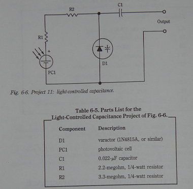
Fred wrote;"Then of course there are varicap diodes (all reverse biased diodes can be used as variable capacitances simply by changing the reverse DC voltage across them).

Invisiblejelly writes:"Yes I was aware of this method of tuning an oscillator I used this method while messing around with Mr Harrison's 'minimum theremin' I turned this theremin into a light based (almost!) playable theremin by changing the frequency by using an led torch on a solar cell with a circuit similar to the one below.


Posted: 6/17/2012 2:47:27 AM
FredM

From: Eastleigh, Hampshire, U.K. ................................... Fred Mundell. ................................... Electronics Engineer. (Primarily Analogue) .. CV Synths 1974-1980 .. Theremin developer 2007 to present .. soon to be Developing / Trading as WaveCrafter.com . ...................................

Joined: 12/7/2007

Invisiblejelly writes:"I thought of using a disc with a magnet mounted on it attached to a turnable knob on top of theremin box"

Worth a try, Invisiblejelly ! - Would be most interesting to know how it goes!

Also, I just want to say sorry for hijacking this thread so completely! - Your original posting here brought up an issue which is, IMO, almost completely neglected - the effect of magnetics on theremin operation, and methods of designing / using magnetic with theremins.

Fred.

You must be logged in to post a reply. Please log in or register for a new account.