I've spent several fruitful days working on my Excel Theremin Simulator and wanted to share it and the results here with those interested. I was going to post it over in the original "Theremin Construction" area, but thought this new "Technical Theory" area was more appropriate.
http://www.mediafire.com/?lhgeyr43xx341gn
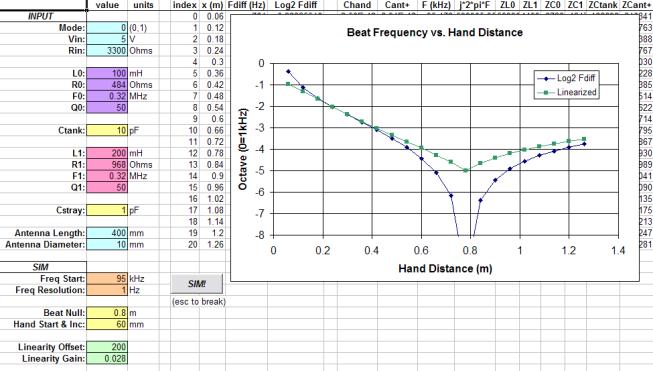
The big change is the "Full Sim" worksheet: I combined the frequency response simulation with the antenna & hand simulation, so antenna geometry sets the bulk capacitance and hand response. Resonance is found via a successive approximation method. Plug in all the circuit and antenna parameters, hit the "SIM!" button, and stand back! Audible output frequency (octaves) vs. hand position is graphed (below is the response of my proposed next gen AFE, operating at ~1/10 the frequency of the original):

"Full Sim" also has a simple linearizer based on the square of the distance from an intermediate point. This tracks quite well when moving the beat frequency null position and is something I will explore in my (mostly) digital Theremin prototype.
I fixed an error in the tank_mode=1 resonance detection (now @ falling 0 degrees).
I added a Bournes 8250 Series inductor specs worksheet for quick reference.
Please also note that my initial simulation of the EW was flawed due to my not taking the high impedance of the tank drive into account. Using the 2N3904 Early Voltage, I estimate this to be in the neighborhood of 38k ohms. The AC currents are quite a bit lower, and tank resonance Q is quite a bit higher than I initially reported. The EW is a strange beast...
I'd be interested in any feedback. For a new design, start with the "Frequency Response" worksheet and use the resonance point to set the "Freq Start" value on the "Full Sim" worksheet. Happy simulating!
(I want to credit FredM for the original idea of combining these two sims - thanks Fred!)

