Excel Theremin Simulator v4

Posted: 10/12/2012 4:24:31 PM
dewster

From: Northern NJ, USA

Joined: 2/17/2012

I've spent several fruitful days working on my Excel Theremin Simulator and wanted to share it and the results here with those interested.  I was going to post it over in the original "Theremin Construction" area, but thought this new "Technical Theory" area was more appropriate.

http://www.mediafire.com/?lhgeyr43xx341gn

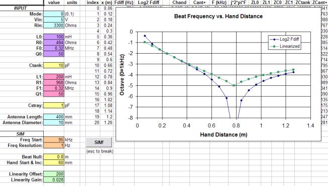
The big change is the "Full Sim" worksheet: I combined the frequency response simulation with the antenna & hand simulation, so antenna geometry sets the bulk capacitance and hand response.  Resonance is found via a successive approximation method.  Plug in all the circuit and antenna parameters, hit the "SIM!" button, and stand back!  Audible output frequency (octaves) vs. hand position is graphed (below is the response of my proposed next gen AFE, operating at ~1/10 the frequency of the original):

"Full Sim" also has a simple linearizer based on the square of the distance from an intermediate point.  This tracks quite well when moving the beat frequency null position and is something I will explore in my (mostly) digital Theremin prototype.

I fixed an error in the tank_mode=1 resonance detection (now @ falling 0 degrees).

I added a Bournes 8250 Series inductor specs worksheet for quick reference.

Please also note that my initial simulation of the EW was flawed due to my not taking the high impedance of the tank drive into account.  Using the 2N3904 Early Voltage, I estimate this to be in the neighborhood of 38k ohms.  The AC currents are quite a bit lower, and tank resonance Q is quite a bit higher than I initially reported.  The EW is a strange beast...

I'd be interested in any feedback.  For a new design, start with the "Frequency Response" worksheet and use the resonance point to set the "Freq Start" value on the "Full Sim" worksheet.  Happy simulating!

(I want to credit FredM for the original idea of combining these two sims - thanks Fred!)

Posted: 10/12/2012 7:29:27 PM
FredM

From: Eastleigh, Hampshire, U.K. ................................... Fred Mundell. ................................... Electronics Engineer. (Primarily Analogue) .. CV Synths 1974-1980 .. Theremin developer 2007 to present .. soon to be Developing / Trading as WaveCrafter.com . ...................................

Joined: 12/7/2007

Dewster, this is really great work!

I spent several weeks trying to do something like the above - got desperately out of my depth.. Nearly sent you my spreadsheet to debug, but before I did I discovered my error and it was so major that I gave up.

This should make designing front-ends a lot simpler. I have not had a chance to really put the sheet through its paces (thanks for emailing it to me ;-) - And I am interested in computing the (theoretical) linearity of the Lev front-end, so will give it a pounding later ;-)

Several fruitful days ? LOL - This is where my maths inadequacy really shows - I spent several weeks, and got nowhere!

Fred.

Posted: 10/12/2012 10:26:55 PM
dewster

From: Northern NJ, USA

Joined: 2/17/2012

Thanks Fred!  It took me days to do it after thinking about it for a week!  And I was building on an established base, so it wasn't too overwhelming.  Most of it is just combining complex impedances (Zr=R, Zl=sL, Zc=1/(sC) where s=jw) and dealing with the overly verbose complex number constructs in Excel.  Looking back on my old PLL simulations it seems I've forgotten more VB (which is used to loop the successive approximations) than I know now!
Excel is kind of a dog, being geared more towards business, with an engineering bag on the side.

Rather than using the one I emailed you, you should download the latest one.  It has a much less fussy null point setting, and also has the simple linearizer.

I can't say I've put too many values into it, though I've certainly played with the EW design and my own AFE quite a bit.  I've never seen anything out of the ordinary in the way of non-linearity other than a general higher sensitivity closer to the antenna and lower farther away.  I think the latter is usually dealt with by the bulk position of one's body.

As a result of playing around with the AFE in the spreadsheet, I've made an order for inductors 100x larger than the ones I'm using now (1mH => 100mH).  Two in the antenna and one in the tank should lower the operating frequency by ~100, lower the current by at least 25, and increase the digital sensitivity by ~3x.  It'll save ~$3 by having two fewer inductors in the antenna.  (Is there any reason others here don't seem to use the Bournes 8250 series inductors?)

And I probably sound like a broken record, but the more I play around with the EW design in the spreadsheet the less I like it.  I'm guessing, but perhaps spectral purity was a goal?  So an oscillator with zero degree feedback was selected, giving a parallel LC tank with drive and sense at the same point. I'm not a huge oscillator expert, but from what I've read these seem to be low gain designs with specific conditions at start-up to get them oscillating.  Low gain can lead to amplitude variation with loading.  This just doesn't strike me as the most ideal thing to attach a huge, similarly tuned series LC (linearizing coil & hand capacitance) circuit to.  The best way to stimulate a parallel LC tank is via a high impedance, like a current source, so as not to degrade the Q.  So the collector of an NPN was selected to do this, but that means the transistor DC bias current is flowing through the tank coil.  Anyway, if spectral purity is one's stated goal, one could easily find oneself on this road, making the same decisions, and ending up with something very similar to the EW front end.  But if spectral purity isn't so important (?) it seems there are much better oscillator topologies out there to pick from.

Posted: 10/12/2012 10:46:47 PM
dewster

From: Northern NJ, USA

Joined: 2/17/2012

I hope no one thinks I'm trying to get their goat, or rag on Bob M. with my criticisms of the EW oscillators.  After all they do work, and Bob was no slouch when it came to this kind of thing.

Posted: 10/13/2012 2:26:55 PM
ILYA

From: Theremin Motherland

Joined: 11/13/2005

...I'd be interested in any feedback...

Coil calculation (turns, diameter, etc.) would be desirable for this beautiful heap. Just to be on hand.

Posted: 10/13/2012 6:11:01 PM
FredM

From: Eastleigh, Hampshire, U.K. ................................... Fred Mundell. ................................... Electronics Engineer. (Primarily Analogue) .. CV Synths 1974-1980 .. Theremin developer 2007 to present .. soon to be Developing / Trading as WaveCrafter.com . ...................................

Joined: 12/7/2007

"I hope no one thinks I'm trying to get their goat, or rag on Bob M. with my criticisms of the EW oscillators.  After all they do work, and Bob was no slouch when it came to this kind of thing." - Dewster

The EM was designed for hobbyist construction and publication in EM magazine, and as I understand it, became the EW in unmodified form, and went on to become the most prevalent theremin on earth.

But it is not one of Bob Moogs great designs - It does the job, is easy to construct, is cheap, the oscillators are quite stable and by comparison to others extremely reliable - It is fit for its original purpose.. But Bob has designed far better oscillators for the E-Vox and E-Pro. The EW is not a "Pro" design, and I think that it really doesnt show Bob at his best!

Until discovery of the way the FET Lev oscillator works, I advocated the EW oscillator as a good design - I have never had problems with it. I now think the Lev oscillator MAY be better - But I havent built one yet other than in simulation, and we really need to have some actual circuits run hard before any claims are made.

So right now, I would still probably advise a newbee to use the EW osc - For one thing, Fets need careful handeling.

Fred.


Posted: 10/13/2012 10:34:42 PM
dewster

From: Northern NJ, USA

Joined: 2/17/2012

"Coil calculation (turns, diameter, etc.) would be desirable for this beautiful heap. Just to be on hand."  - ILYA

Here ya go:

http://www.mediafire.com/?x13mnflp8gm7kre

I added a coil calculator worksheet to the end.  You put in the wire diameter, form diameter, how many turns, and operating frequency and it spits out inductance, resistance, Q, etc. Only works for single layer, tightly wound, air core coils, but that covers most homebrew Theremin coils, correct?

Also added an AWG diameters worksheet.

[EDIT] Oops, found a minor error in the new coil calculator, fixed and updated link above.

Posted: 10/14/2012 10:50:58 AM
FredM

From: Eastleigh, Hampshire, U.K. ................................... Fred Mundell. ................................... Electronics Engineer. (Primarily Analogue) .. CV Synths 1974-1980 .. Theremin developer 2007 to present .. soon to be Developing / Trading as WaveCrafter.com . ...................................

Joined: 12/7/2007

Hi Dewster,

Having played a bit (not much) with your spreadsheet now, well - what can I say .. ?.. IMO Its probably the most useful tool for theremin designers ever created, thats about all I can say! - Certainly the most useful I have found - and far more useful than anything I have ever put together!

This spreadsheet fills in the "simulation gap" - The main problem area in designing theremin front-ends is that one has a huge range of possible selections which will work - different operating frequencies, tank inductances, tank capacitances etc - The antenna equalizing inductance has been the simplest to calculate once the frequency has been defined - but selecting the optimum tank capacitance and inductance to give best linearity has been a rule-of-thumb / hit-and-miss procedure, with no easy way of computing linearity..

Yeah - This spreadsheet (well, its more than a spreadsheet - the VB makes it a program) does it all -

Much respect for the work you put in and the superb implementation! This is BRILLIANT!

..... Now my request.. This would not have been thought of had the operation of the Lev oscillator not been decoded - Never would have dreamed of a series tank resonator split into two coupled series inductors with the antenna resonator strapped across one of these inductors..

It is (as far as I can see) not possible to simulate this configuration with your program at present - I would really love to be able to do this - to be able to compare operation at the RCA's 172kHz with operation using higher frequencies (smaller tank inductors / capacitors).. and perhaps even designs where the two inductors are "unbalanced" - as in, different values.

It looks to me like all the 'bones' are in place to facilitate the above - except for the inductor coupling.. This would require input of an AL (permeability) value and input of the value of each series tank inductor - from these, total series inductance could be computed.. The antenna resonator would need to be coupled across one of these inductors (call it L2) and the "simulation" then run with frequency being computed for this new configuration - Mode "Lev" if you like ;-)

If you could do the above without too much effort, we would be able to compare Lev's linearity with what we have been used to - I personally think we will see a huge improvement.

Fred. 

ps - Discussion about developing a tool like you have just provided was happenning 2+ years ago on Element-14 "Theremin Development" group - but never went anywhere.

I have announced your spreadsheet there just in case anyone still looks at that group! ;-)

http://www.element14.com/community/groups/theremin-development?view=discussions&start=0

Posted: 10/14/2012 4:35:46 PM
dewster

From: Northern NJ, USA

Joined: 2/17/2012

Fred, you're making me blush!

I've given your Lev topology simulation request some thought, but I can't say I completely understand transformers.  (This project is forcing me to explore fundamental EE stuff that I really should know.)  Looking around the web I found this:

http://www.beigebag.com/case_xfrmer_1.htm

From that:

V1 = V2 * n
I1 = I2 * (1 + Zload/(s*L2)) / n
Z1 = Z2 * n * n / (1 + Zload/(s*L2))

Where:

1, 2 = primary winding, secondary winding

n = turns ratio, primary/secondary

Zload = complex load impedance across secondary

L2 = inductance of secondary

s = jw = j*2*pi*Freq

The third equation is obviously found by combining the first two, Z=V/I.

So it seems a (idealized) transformer is a simple transformer of voltage, but a complex transformer of current and impedance.  Still trying to wrap my brain around the connection of a capacitor from one winding to the other.

Just the simulation via spreadsheet of two inductors (with parasitics) and two capacitors is rather cumbersome and laborious.  I wonder if it might be easier to make a model of the antenna & hand capacitance in spice and use this in a Theremin circuit simulation?  The equations are pretty simple.  Perhaps make it a voltage controlled capacitance, with voltage=hand distance, and do a slow voltage sweep?

Posted: 10/14/2012 5:44:46 PM
FredM

From: Eastleigh, Hampshire, U.K. ................................... Fred Mundell. ................................... Electronics Engineer. (Primarily Analogue) .. CV Synths 1974-1980 .. Theremin developer 2007 to present .. soon to be Developing / Trading as WaveCrafter.com . ...................................

Joined: 12/7/2007

Hi Dewster,

As I see it, the capacitor in the centre of the two inductor series LC behaves (from a simple analysis perspective) like a capacitor connected in series with a single inductor ..

(fig 1) ----WWW-----||------WWW----  =   (fig 2) ------WWW-----||------- (W's are the inductor)

Now the only complexity is that in fig 1, the inductors are magnetically coupled.. this results in the total inductance being (far) greater than if they were not coupled - uncoupled, the inductance of the equivalent in fig 2 would simply be the sum of the two inductances in fig 1.

I do not think this is really a "transformer" problem - its an effective turns problem - take a former, and wind 100 turns on it - the inductance you get is dependant on permeability.. Take 2 of these seperate coils, wire them in series, and you will get twice the inductance of one..

But take the same former and wind 200 turns on it, and you will get a greater inductance than you get from the 2 seperate coils. All that the Lev tank coil is effectively is the "200 turn" inductor split with a capacitor connecting the two halves - this forms both the series resonant circuit and gives access to a comparatively low inductance across which the antenna circuit is strapped, and the resonance being determined by the far greater combined inductance - IMO, its really brilliant!

The interesting bit is that with the Lev front-end, one of these coupled (tank) inductors has the antenna resonant circuit strapped across it - this effectively puts a "virtual" un-coupled inductor across one of these coupled inductors - this inductance (an a correctly tuned system) being proportional to the capacitance being seen by the antenna.

With the Lev design, the individual inductances are about 160uH and the combined inductance is about 600uH - Effective reduction of one of these inductors by the antenna resonator will impact on the total inductance (which determines the oscillator frequency) but exactly how this scheme behaves in terms of affecting the response is bending my brain a bit - and I am reasonably sure that there is no way to get a real reflection of this response on your spreadsheet.

I will try to determine the relationships - but this is maths.. so I may go quiet for a few weeks! ;-)

Unless someone posessing more than the tiny 8 bit 4mip processor I have in my brain for processing maths, helps out!

;-)

Fred.

You must be logged in to post a reply. Please log in or register for a new account.