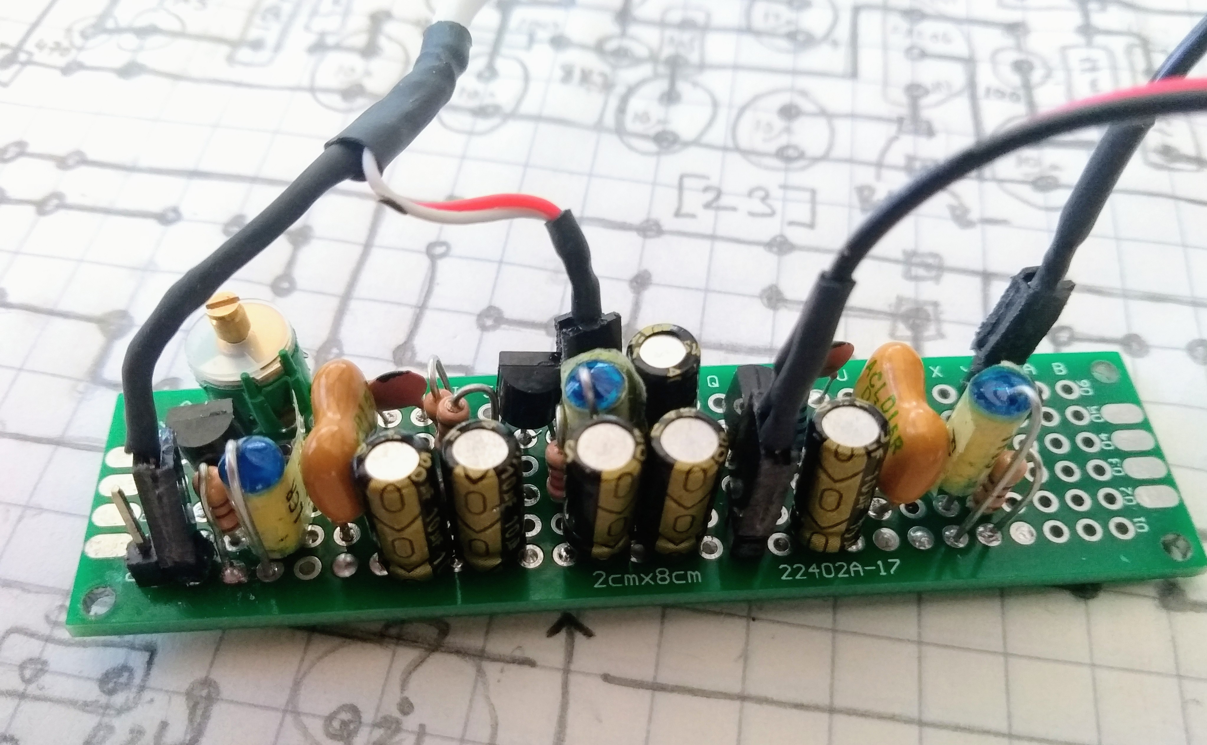
My New Year gift to TW: A new theremin circuit

Posted: 4/10/2018 11:55:33 AM
renyhp

Joined: 4/2/2018

I am not very active but dislike lonely threads. 

I appreciate your intervention, thank you

Home PCB making is a good thing to learn. I would never recommend construction of a high frequency analog project like this on one of those white proto boards due to unwanted capacitance coupling between components.


I understand that. I know that building a theremin is better done on a PCB than on a breadboard. In fact, since I have very little experience in soldering but I have used breadboards a lot in the past, I was thinking about trying to make this circuit on a breadboard first, before go further to solder it. Besides, in this thread and on the internet there is a lot of evidence that on a breadboard it can work as well.

In theremin design an ugly sound vs a beautiful sound are only separated by a thin margin of knowledge. 

 
Now that is exactly my point. What I got is not even close to ugly sound, nor is the noise I'm getting in any way affected by my hand. The circuit as it is now on my desk is very far from being a theremin. Since Thierry's idea, undoubtedly, does work, I must assume something in my implementation has gone wrong.
But is that really the use of a breadboard? Wouldn't that only affect the quality of the sound, instead of the working of the whole circuit? Also, if it's the breadboard, by disassembling the circuit and putting it together again in different rails I should hear some difference, or, if I'm very lucky it should even get better. This behaviour, though, I'm absolutely not seeing.

Posted: 4/10/2018 12:42:02 PM
Thierry

From: Colmar, France

Joined: 12/31/2007

Just a few quick remarks (not much free time actually):

5V is not enough supply voltage, stabilized 6V are needed, that's why there is a 7806 voltage regulator in the schematic. With the original 5484 FETs which have been explicitly chosen for their extremely low pinch-off voltage of -1.5 to -3V, the circuit is known to work from 6V on. You decided to use incompatible FETs with a pinch-off voltage which can even go beyond -6V. How can you expect an oscillator to work if the required source-gate cut-off voltage of these inappropriate components exceeds already the available power supply voltage? 

Besides all that, a quick check with your oscilloscope would have shown you that the oscillators do not work this way because of too high quiescent current due to a too low Vgs.

C44 has to be identical to C14 and both have to be 3.3pF. If not sure about their marking, take your capacitance meter and check them.

Thus, build the power supply section as required by the design, buy the needed FETs, and then write back, because then there are other issues to fix like the circuit layout: In Theremin circuits, each 1/100 of a pF matters. Breadboards are a no-no. And the antenna connection has to be placed far away from all other wiring, that's why on my PCB design, it is in a corner. With the antenna wire close to the audio cable, and the antenna not mounted vertically above the PCB, it can simply not work.

Posted: 4/10/2018 12:55:46 PM
dewster

From: Northern NJ, USA

Joined: 2/17/2012

Leave every other row clear on the breadboard, and set the breadboard on a plastic box - both of these will reduce parasitic capacitance.  If the capacitor is small and only has a '3' on it, it most likely is 3pF.  What inductors are you using?  I've had poor experience with the types wound on ferrite bobbins.  Also, get your hands on a scope, if only for a long enough to debug things, without it you're flying blind.

Posted: 10/15/2018 7:55:04 PM
tws4308

From: Portland, Oregon

Joined: 10/15/2018

Hi Thierry, I realize I'm late to the party on this thread, but I'm excited to build this circuit.  Full disclosure, I am a beginner and have very limited knowledge in circuits/electronics and how they work. This project will be a great learning experience :-)

1) For my variable capacitor, I am using the Sprague-Goodman GYA22000 (2.2-22pF).  I was expecting it to have two leads, but it has three (two rotors and one stator).  How do I wire this? Do I leave one of the rotors floating/unconnected?

2) I saw the comment "The audio out has line level and high impedance and thus can not drive a speaker directly.  It is intended to be connected to the inner wire of a shielded cable (shield connected to GND) which transports the signal towards an external amplifier."
I'm trying to make sense of this...by "inner wire," do you mean a single wire that is shielded (serious question, I know it may sound silly)?  

Could an "external amplifier" be, for example, a guitar amplifier?  If so, would I just connect the shielded audio/inner wire to, say, a female 1/4 inch connector, and then simply use a standard instrument cable to hook up to the guitar amp?

Thanks so much for your help.

Posted: 10/15/2018 8:11:02 PM
Thierry

From: Colmar, France

Joined: 12/31/2007

1.) yes, leave one rotor pin unconnected.
2.) all instrument audio cables for guitars etc have one single inner conductor and a grounded shield around.

A guitar amplifier will basically work but not sound very well. Guitar and bass amplifiers are optimized to be fed from these magnetic pickups and thus have a relatively high input impedance, be somewhat too sensitive (risk of unwanted overdrive and distortion when being fed from a theremin) and will have a bent frequency response to compensate the inductive effects of the pickups. So, there is a risk that the theremin will sound muffled and distorted. Better use a keyboard amplifier. These can deal with line level signals at the input and have a flat frequency response. I’m using a Bose L1 compact PA system, not only for performing on the Theremin but also for testing Theremin and related circuits.

Posted: 10/24/2018 9:11:43 PM
tws4308

From: Portland, Oregon

Joined: 10/15/2018

Great, thank you very much!  A couple more things:

1) I'm looking for a suitable veroboard, and per your instructions, I am avoiding the strip boards and boards with square holes/dots.  However, as someone new to electronics, I was quite surprised at the wide variety of boards available on veroboard.com.  I noticed that many of the boards have round holes/dots, but the dots are enclosed inside square pads (see link below):

https://veroboard.com/product-category/veroboard/by-type/perfboard/

What are these square pads, and do I need them?  Is there a specific board/product you can recommend?

2) Back to the audio out...my plan is to create a wooden enclosure for the circuit, with the audio out consisting of a single conductor wire with grounded shield, soldered to a mono female 3.5mm jack.  The jack will be mounted to the wooden enclosure, so that I can plug a male mono 3.5 mm cable into it to transport the signal to the auxiliary input jack of an external speaker (In my case, the Bose Soundwave IV speaker).  Since my speaker is stereo, I think I'd also have to get a mono to stereo adapter.  

Is this approach possible, or am I trying to "drive the speaker directly," which you said will not work due to high impedance?

I think I understand your keyboard amplifier suggestion, but after attempt to build/tweak/perfect this circuit, I'd like to give it as a gift and want to avoid having to also provide an amplifier :-)

I feel silly asking some of these questions here, but please be assured that I am here to learn and greatly appreciate all of the knowledge in this forum.  Thanks!  

Posted: 11/24/2018 3:45:59 PM
Silverloz

From: Stockport, England

Joined: 11/24/2018

Hi Thierry, I would just like to say thank you for designing and publishing your straightforward-to-follow theremin circuit. I have built it on prototyping matrix board in a layout that closely follows your pcb layout. My son and I had great fun building it together and we now just need to mount it all in an old cigar box  Once again, thanks.

Posted: 1/1/2019 6:20:00 PM
Tomislaw

Joined: 1/1/2019

I have recently came across your theremin circuit and I found it very interesting - thanks for posting it. I've always wanted to build a replica of Jimmy Page's theremin which apparently was the infamous Sonic Wave unit. Unfortunately, no schematics have been made available so far. There are several gut shot pictures, though, which show an extremely simple circuit mostly consisting of two Texas Instruments 2N3437 JFET's and variable coils. Franklin oscillators perhaps? I was thinking about using JFET oscillators from your design and putting a simple diode dectector there instead of the mixing stage to make the sound a bit rough as in the original device.

Several years ago I built another theremin which sounds very nice to me but is a bit annoying to use. That's the one that was described in the "Everyday with Practical Electronics" magazine from 1995. Quite a simple circuit using bipolar transistors and fixed inductors running at around 1.3MHz, but in practice with a tendency to drift and run away despite using quality components. I added a variable air capacitor from an old radio to be able to tune it up. Now a friend of mine has been pestering me to build one for him and I'd rather get him a device which doesn't drive you crazy every time you turn it on and find out it's not working again. I thought switching to JFET oscillators running at three times lower frequency would be a good idea, but on the other hand I'd rather not lose the slightly distorted output signal. And it plays fine through the guitar amp and delay, but hey, this theremin is supposed to sound quite mean.
I just ordered a batch of 2N5484 transistors and I'm going to give it a go.

Best regards,
Tomi

Posted: 4/25/2019 9:11:10 AM
Norberto niteat

Joined: 4/25/2019

Well, I'm about to try to build this Thierrymin... After reading almost all the thread and as I'm having almost no time to finish the project I'm worrying of not having access yo any suggested JFet.

2n5457 is my only option.

"But the cut-off voltage should not exceed the half of the supply voltage (6V), thus only a cut off voltage of max. -3V is acceptable because otherwise the oscillators would not start and the demodulator stage would not output enough AF signal."

So, probable I'm wrong, but it seems to me (I'm such an ignorant)  that if I give more supply voltage, let's say 12V, then there'll ve no problem because of the Vgs(off) of the 2n5457 is -6V at Max.

I can't tell the side effects this would bring, so please let me know. Thanks for reading.

Posted: 4/25/2019 10:12:08 AM
Thierry

From: Colmar, France

Joined: 12/31/2007

I'm getting tired about all these people who want to use different JFETs from those for which this circuit has beed designed and which have been tested and are approved...

The 2N5484 are easily available. When I search for these on eBay, I get 6 results from sellers within the EU, and 26 from sellers outside the EU. Where is the problem?

The cut-off voltage of a FET is not the only criterion in an oscillator circuit, there is a meticulously balanced thing between forward gain which is responsible for the startup behavior and the oscillator amplitude, power dissipation and temperature stability. Changing something which rises the amplitude like increasing the supply voltage will give an ugly sound since the mixer which acts as a non-linear filter and as a linear low pass filter at the same time, will be overdriven. At the same time, doubling the power supply means quadrupling the power dissipation and thus sacrificing the temperature stability.

Instead of trying to modify all but the JFETs, you should diligently plan your project, buy all the needed components as required, and then build it. That is called serious engineering. Hasty throwing together of components, which one finds just so in the drawer, is definitely no option!

You must be logged in to post a reply. Please log in or register for a new account.