The heterodyning upon which the pitch side of most analog Theremins are based creates a null, or zero beat, when the player's hand reaches some distance from the pitch antenna. I see the null as prima facie evidence of non-linearity, because equal hand distance movements, wherever they are located in the playing space, should produce equal ratios of pitch, and zero can't be produced ratiometrically. Ideally (in terms of linearity, not necessarily how any particular player desires their dream Theremin to behave) we should get lower pitches moving away from the pitch antenna, and never reach zero Hz. Alternatively, pitch might have some hard lower limit below which it couldn't drop.
Approaching the antenna, again in an ideal linearity sense, the pitch should give equal ratios of pitch until one is right at the antenna, whereupon some maximal pitch should be reached.
Just thinking aloud. Heterodyning is fascinating in that it gives you a fairly linear sounding mid field from a really complicated input. I can't help but wonder though: if one were able to use more complex functions to interpret the LC pitch data, and starting out with a fresh piece of drafting paper, might one find oneself using something other than heterodyning (or the mathematical equivalent, subtraction) as the first processing step? I've played around a bit with the hand capacitance vs. distance formula in my Theremin spreadsheet, but I think it needs to be simplified somewhat in order to produce a practical substitution for the heterodyning function (e.g. it doesn't necessarily need the input constants to correspond to actual physical dimensions).
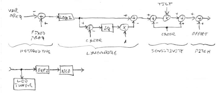
My current approach to linearity is to take the difference frequency number from the DPLL loop filter integrator (~heterodyning), take the log base 2, subtract from it some constant ("CENTER") that roughly corresponds to the mid field value, square and scale it ("A"), and subtract it from the initial log base 2. The result of this, since it is in the log domain, can have a simple multiplicative factor that increases/decreases the sensitivity ("TILT") and a simple additive factor that increases/decreases the relative pitch ("OFFSET"). The result of this is sent to the LED tuner, and taking the EXP2 of it feeds the NCO or software oscillator. Here is a block diagram that might make the process clearer:

(Not represented in the text nor diagram is a trivial "sign" function that makes the linearizing factor follow the sign of the log2 input. Also not represented is low pass filtering of the input frequency value.)
While only some of this has actually been up and running on my prototype, I believe this approach is "good enough" to put in a fairly ideal Theremin. But starting out with the difference frequency in the first place may not be the most elegant approach. In particular, non-linearities very close to and very far from the antenna still exist, and may behave rather oddly should the null point drift significantly.
The beauty of the above approach is that there are only two rather simple controls for linearity, "CENTER" sets the balance between near field and far field linearization, and "A" sets the linearization strength. "CENTER" might be set by pressing a button with the hand at mid field, with the result fine tuned via up/down buttons or a knob. "A" might be set manually (again via up/down buttons or a knob) by comparing mid field and near field pitch behavior, or by "tuning out" weird behavior very near the pitch antenna.

