Null Hypothesis

Posted: 1/9/2014 3:28:07 PM
dewster

From: Northern NJ, USA

Joined: 2/17/2012

The heterodyning upon which the pitch side of most analog Theremins are based creates a null, or zero beat, when the player's hand reaches some distance from the pitch antenna.  I see the null as prima facie evidence of non-linearity, because equal hand distance movements, wherever they are located in the playing space, should produce equal ratios of pitch, and zero can't be produced ratiometrically.  Ideally (in terms of linearity, not necessarily how any particular player desires their dream Theremin to behave) we should get lower pitches moving away from the pitch antenna, and never reach zero Hz.  Alternatively, pitch might have some hard lower limit below which it couldn't drop.

Approaching the antenna, again in an ideal linearity sense, the pitch should give equal ratios of pitch until one is right at the antenna, whereupon some maximal pitch should be reached.

Just thinking aloud.  Heterodyning is fascinating in that it gives you a fairly linear sounding mid field from a really complicated input.  I can't help but wonder though: if one were able to use more complex functions to interpret the LC pitch data, and starting out with a fresh piece of drafting paper, might one find oneself using something other than heterodyning (or the mathematical equivalent, subtraction) as the first processing step?  I've played around a bit with the hand capacitance vs. distance formula in my Theremin spreadsheet, but I think it needs to be simplified somewhat in order to produce a practical substitution for the heterodyning function (e.g. it doesn't necessarily need the input constants to correspond to actual physical dimensions).

My current approach to linearity is to take the difference frequency number from the DPLL loop filter integrator (~heterodyning), take the log base 2, subtract from it some constant ("CENTER") that roughly corresponds to the mid field value, square and scale it ("A"), and subtract it from the initial log base 2.  The result of this, since it is in the log domain, can have a simple multiplicative factor that increases/decreases the sensitivity ("TILT") and a simple additive factor that increases/decreases the relative pitch ("OFFSET").  The result of this is sent to the LED tuner, and taking the EXP2 of it feeds the NCO or software oscillator.  Here is a block diagram that might make the process clearer:

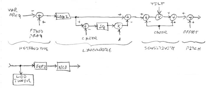
(Not represented in the text nor diagram is a trivial "sign" function that makes the linearizing factor follow the sign of the log2 input.  Also not represented is low pass filtering of the input frequency value.)

While only some of this has actually been up and running on my prototype, I believe this approach is "good enough" to put in a fairly ideal Theremin.  But starting out with the difference frequency in the first place may not be the most elegant approach.  In particular, non-linearities very close to and very far from the antenna still exist, and may behave rather oddly should the null point drift significantly.

The beauty of the above approach is that there are only two rather simple controls for linearity, "CENTER" sets the balance between near field and far field linearization, and "A" sets the linearization strength.  "CENTER" might be set by pressing a button with the hand at mid field, with the result fine tuned via up/down buttons or a knob.  "A" might be set manually (again via up/down buttons or a knob) by comparing mid field and near field pitch behavior, or by "tuning out" weird behavior very near the pitch antenna.

Posted: 1/9/2014 9:53:56 PM
FredM

From: Eastleigh, Hampshire, U.K. ................................... Fred Mundell. ................................... Electronics Engineer. (Primarily Analogue) .. CV Synths 1974-1980 .. Theremin developer 2007 to present .. soon to be Developing / Trading as WaveCrafter.com . ...................................

Joined: 12/7/2007

Hi Dewster -

Interesting point about the impossibility of absolute linearity on the bass end, as you say, to be truly musically linear, each "octave distance" should be equal, and therefore when one gets to say 20Hz, the next "octave distance" (say 10cm for argument) should be 10Hz, then 5Hz etc... Zero should never be reached.

In reality though, provided one gets reasonable linearity down to say 16Hz, what happens beyond that doesnt matter.... Had this argument once with a manufacturer who claimed 10 octaves, but was including sub-16Hz in the calculation - Ok, 8Hz is still includable - but below that its nonsense..

With analogue theremins the "null" point is often more to do with oscillators pulling themselves into lock - In reality, without oscillators pulling, the bass end tends to be stretched (octave distance gets greater) and one can end up with a lot of sub-16Hz "playing" area - but whether this is heard will entirely depend on the waveform and audio circuitry - One may hear the higher harmonics of an 8Hz difference, and one may hear a 3Hz 'clicking' or 'thumping' and one may never get to a 'null' position even when walking away from the theremin.. I think some theremins go "silent" long before "null" simply because the frequency response of the audio circuitry (both in the theremin and/or external)attenuates the signal to inaudible levels - particularly if the signal has low harmonic content.. With my H1's I had to deliberately couple the oscillators (couple of pieces of wire twisted together - I had put pads on the PCB specifically for this - only some theremins needed it though!) as they would "tick" otherwise because my auto-muting circuit would jitter..

But with unconventional (such as the 91 series or my upside down topology) or digital topologies, "null" is a function of the tuning of some independent oscillator, and can be set anywhere (the 91 drives a voltage controlled synthesis engine, so one could take the voltage derived from the capacitance and offset this to any frequency at the "null" position - With mine the same is true, even though I produce audio through heterodyning)

Controls for linearization are an interesting topic - one I have sweated over - your idea about placing a 'mid' point and a "strength" control is an approach I had not thought of - My thinking has been to forget the 10cm closest to the antenna - because I have (and I am sure you can have) an adjustable 'span' I was looking at having a control to set the frequency at 10cm, and a control to set the frequency at say 70cm, and a single control to mix "linear" and "natural" antenna responses - the "linear" response would be an analogue processed shaped response which somewhat over-compensated for linearity [using a multiplier to produce a specifically distorted square square 'type' law - all working in simulation only! :-] so by adding these two responses adjustably one can go from extremely non linear (compression at the high end - as per any non compensated theremin) through to musically linear at say mid position, with a bit more if any more was needed..

My plan is to have register switching (perhaps 6 registers), so one could set say a top frequency of 1kHz and bottom frequency of 1024Hz (3 octaves) in position "4" and transpose this down to 16Hz - 128Hz in position "1" or up to 512Hz to 4096Hz in position "6" .. (I am inclined to thinking 2kHz is probably as high as is needed though..) Obviously, if one extends the span 6 octaves then some register positions would be redundant - and this area is giving me some bother, as I think I may need a digital user interface to simplify the span / register relationships... but the DUI route almost dictates that I put other functions under its control to justify having it - and that goes against my inclinations...

But in general, it seems we are both going in the same sort of direction with our thinking

Fred.

Posted: 1/10/2014 1:25:09 AM
dewster

From: Northern NJ, USA

Joined: 2/17/2012

"Controls for linearization are an interesting topic - one I have sweated over.."  - FredM

It's likely we've both spent way too long on it!

"...My thinking has been to forget the 10cm closest to the antenna - because I have (and I am sure you can have) an adjustable 'span' I was looking at having a control to set the frequency at 10cm, and a control to set the frequency at say 70cm, and a single control to mix "linear" and "natural" antenna responses - the "linear" response would be an analogue processed shaped response which somewhat over-compensated for linearity [using a multiplier to produce a specifically distorted square square 'type' law - all working in simulation only! :-] so by adding these two responses adjustably one can go from extremely non linear (compression at the high end - as per any non compensated theremin) through to musically linear at say mid position, with a bit more if any more was needed..

I never found a satisfactory to linearizing pitch response directly in the heterodyned domain.  Polynomial / square correction solutions seem overly sensitive to set point and gain (in simulation).  Arbitrary solutions like splines need many points to be effective and not give too "lumpy" results - linear interpolation is worse in this regard.  And then there is the much thornier issue of the average user understanding the process and controls well enough to make the final result an effective one.  Reducing the controls as you propose to one or two that do something intuitively obvious, even if it means compromising the result somewhat (but please don't think that I'm implying your approach is a compromise or otherwise inferior) is likely critical for any success.

Log2 of the heterodyned result makes a square correction fit remarkably well, but it is still somewhat sensitive to set point and gain.  I need to do log2 anyway for the sensitivity, offset, and tuner, so doing it earlier isn't a big deal.  (It's weird how long I resisted doing that - it's important I suppose to actually solve the problem at hand one way or another before considering implementation details.)

All of this makes me wonder if there is a more elegant solution when heterodyning isn't even going on.  If you could hook an LC oscillator to a frequency counter and run the numbers to a PC, what approach would you take?  Does subtraction as a first step make the most sense?  Subtraction produces near and far field non-linearities that must then be dealt with rather artificially.  Working backwards from the LC and hand capacitance calculations, or simplifications of them, may yield a better way to mathematically handle things. 

Though I must say the null point is a very clearly defined thing, around which much of the adjustment and functionality may be structured.  Null moves with drift, adjust the null back to where it "should be" and perhaps other things like linearity correction might fall back into alignment as well.

Posted: 1/10/2014 3:28:17 AM
FredM

From: Eastleigh, Hampshire, U.K. ................................... Fred Mundell. ................................... Electronics Engineer. (Primarily Analogue) .. CV Synths 1974-1980 .. Theremin developer 2007 to present .. soon to be Developing / Trading as WaveCrafter.com . ...................................

Joined: 12/7/2007

"Though I must say the null point is a very clearly defined thing, around which much of the adjustment and functionality may be structured.  Null moves with drift, adjust the null back to where it "should be" and perhaps other things like linearity correction might fall back into alignment as well." - Dewster

Its clearly defined, but is it really meaningful of itself? I have heard lots of what I think is garbage about the magical "null point".. Apart from the effect of oscillator locking, one could I think set the "null" frequency wherever one wants.. One has a variable oscillatot and a fixed oscillator on a conventional theremin, and the requirement for an audio "null" has defined this as an important reference - but if one is not using the difference frequency directly for the audio output, and one is not using oscillator pulling for some linearizing function, then does it matter if the difference frequency at say 60cm is say 1kHz? is not 1kHz as valid a "null" frequency as 0Hz ?

In truth, I dont know the answer - My route is to have a constant phase-locked antenna frequency, and use the CV from the PLL via analogue processing to control a VFO which then heterodynes with the antenna (reference) frequency - my hope is that by having the antenna frequency 'regulated' some of the linearization issues will dissapear (the V-F relationship on the antenna VFO can be trimmed to be shaped / non-linear) and that by getting the VFO relationship 'right' and having a seperate analogue shaper for the "output CV" going to the heterodyning VFO I can get a reasonable adjustable linearity correction on a single knob..

Oh, it wont be absolutely perfect - but I dont believe that any capacitive long range sensing scheme can ever be even close to absolutely perfect unless the environment is absolutely constant - All I want is something at least as good as anything presently on the market, something with adjustable span (I see this as more important even than linearity) and the ability to trim the linearity to a form the player finds comfortable and playable regardless of what the capacitive environment is.

But its all just in my head and in simulation world - I have not found anything that looks like a major problem (the biggest problem is the UI, what to add and what to leave out - it would be lovely to have a graphic EQ type control for linearity - but too complex unless implemented in a DUI, and probably too complex anyway, both for the user and in terms of cost)

I think your approach is about the same level of complexity as I am targeting - A "tuning" and a "tilt" control - I may end up with something quite similar - perhaps a "tuning" and "linearity" control, and either a "span" potentiometer or a switch to set 3 to 7 octaves, and then the register selector - whatever - it comes down to 3 controls for span and linearity whichever way I go. 

"Log2 of the heterodyned result makes a square correction fit remarkably well, but it is still somewhat sensitive to set point and gain. "

Yeah, this is an area which is tricky for me - Span and linearity controls will be somewhat interactive - I dont see it as a major issue (I expect folks to set a span which suits their level of playing, and not often adjust this) but it does incline me to having switchable spans rather than fully adjustable "high" and "low" tunings.. The whole span / linearity thing is all to do with the processing of the PLL CV - A lot comes down to what scheme I employ, at present I am looking at V/Hz type topology, where simple multiplication of the corrected CV should facilitate adjustable span, but this does make pure analogue register switching much more difficult -

The alternative is massively more complex (Multiplying the HF to derive a multiplied difference frequency, then doing F2V on this, then exponentiating this, then adding / subtracting register voltages on this (say) 1V/Octave, then returning this to a seperate HF VFO on which I repeat the whole process to provide a tracking correction signal (effectively another PLL)..

Its all easy if I throw away my "pure analogue" inclinations and go the E-Pro mixed-signal route for register switching.. but I will only do that if I absolutely must for a lower cost version - I have other solutions in mind, but havent fully worked out the details enough to simulate these yet..

Fred. 

Posted: 1/11/2014 4:22:39 PM
dewster

From: Northern NJ, USA

Joined: 2/17/2012

"...I dont believe that any capacitive long range sensing scheme can ever be even close to absolutely perfect unless the environment is absolutely constant..."  - FredM

I agree.  But stepping back a bit, assume you do have a nearly perfect long-range capacitance range sensor that tells you linear distance from the antenna to your hand.  Call this distance "x".  How do we use x to make a Theremin?  We want the frequency "F" to decrease with increasing x.  And our ears perceive pitch logarithmically so we need an exponential function in there somewhere.  Say we desire some highest frequency "Fh" @ x=0, and we want an octave spacing of "OCT" meters:

    x  F
---------
0 Fh
OCT Fh/2
2*OCT Fh/4
3*OCT Fh/8

And so on, so this seems to be the relationship:

(1)  F = Fh * 2^(-x/OCT)

Using the coplanar equation for hand capacitance from an antenna:

            f * E0 * ( L * H )^0.5       ( x + D ) * ( x + H ) 
(2) Chand = ---------------------- * ln[ --------------------- ]
pi x * ( x + D + H )

And the equation for bulk antenna capacitance:

            2 * pi * E0 * L
(3) Cant = -------------------
ln( 2 * L / D ) - k

And finally the resonance point of an LC oscillator:

(4)  Flc = 1 / ( 2 * pi * (LC)^0.5 )

We can try to find a function that gives us our desired Theremin pitch response for reasonably linear changes in x.  In reality we don't have access to x, but we can measure Flc.

We can start by adding the capacitances (2) and (3) and plug the result into (4).  This gives us a relationship between LC resonance and x. 

Then we solve (1) for x and plug that in to get a relationship between LC resonance and Theremin pitch.

But it gets kind of thorny, and I'm wondering if there are simplifications that might yield "close enough" results?  Heterodyning with polynomial (square) correction is one simplified solution - are there others that might work well and not be too sensitive to changing conditions?


Posted: 1/12/2014 1:02:46 PM
FredM

From: Eastleigh, Hampshire, U.K. ................................... Fred Mundell. ................................... Electronics Engineer. (Primarily Analogue) .. CV Synths 1974-1980 .. Theremin developer 2007 to present .. soon to be Developing / Trading as WaveCrafter.com . ...................................

Joined: 12/7/2007

"But it gets kind of thorny, and I'm wondering if there are simplifications that might yield "close enough" results?  Heterodyning with polynomial (square) correction is one simplified solution - are there others that might work well and not be too sensitive to changing conditions?" - Dewster

My "solving" is done somewhat differently, probably because I lack the mathematical abilities - I have played with this stuff on the volume circuiys far more than for pitch - am only really concentrating on pitch now with my new topology..

Forget heterodyning - lets start by getting a changing voltage (or numerical value, but Ill stay with voltage) - plot the curve from antenna to required "null" point - one gets a sort-of square curve over the majority of this span (depends on the sensing circuit - using a series LC driven from a fixed frequency, one can get varying curves dependant on how close to resonance one sets the tuning, and where one tunes this point - as in, either close to the antenna or distant from it)

One has this curve - and drives this into a modifier - A multiplier taking this voltage into both its inputs - A "straight" multiplier will give an output of X^2 but all sorts of other relationships are possible by distorting the multipliers operation or adding another multiplier  - one ends up with an input curve and an output curve - I try to make the output curve as linear (actually, not musically) as possible. With my new topology I can modify the response curve both of the antenna oscillator (from the PLL filter before driving the VFO)[VFO-1] and also seperately modify the curve of this error voltage to drive the (to be heterodyned) VFO[VFO-2] - I am therefore simplifying things a bit by talking only of the voltage to drive VFO-2, but both impact on the result.

Both curves (the original and the processed one) are offset and amplified to the same maximum and minimum values, and a resistive "summer" employed with a potentiometer so that at one extreme one gets the original curve, at the other extreme one gets the processed voltage, and in the mid position one gets a mix of both.(there are more elaborations to control span and register, but I will not go into those ;-)

In simulations (and this is all I have done, the above has not been built for pitch correction - the "principle" has only been used by me on volume circuits, and on these there was only one processing stage as there was no "VFO-1" or for that matter even a VFO-2) I can get quite close to a linear output from the processor, and quite close to an acceptable exponential output to drive VFO-2.. and there is a lot more I can do to the curves, but any further simulation at this stage (untill I have built it and played with it) is a bit pointless. 

I dont think there is a lot one can do about "conditions" (other than directional antennas which do reduce environmental variation / background capacitance variation substantially)..

I suppose (?) that mathematically, the polynomial square is closest to what I am doing - except that I am doing a lot of "fiddle factor" stuff - at present "fiddling" with components in the simulator and examining the resulting curves, but hopefully soon doing this for real on a breadboard - a few of LM13700's tacked between the PLL PD filter and the oscillators will tell me quite quickly whether this is a last worthy attempt at getting my theremin to a state I am happy about, or whether this really is time to give up on distance as a means of controlling pitch.

In terms of maths, I really dont have much idea about what I am doing - but if I get roughly the same input curve (albeit perhaps shifted due to conditions) on production theremins, and have a defined stable adjustable "processor" - well, I only need to get the design of this processor right once - its a reasonably straight-forward circuit with not-too-critical component tollerances, unlike antenna-end stuff!

Fred.

Posted: 1/14/2014 1:22:15 AM
dewster

From: Northern NJ, USA

Joined: 2/17/2012

I think I started this thread to torture myself anew! :-)

I'm going back over (and over) ground that's probably better off put to bed at this point.  Square compensation in the log2 domain works really well in simulation, and sensitivity and offset are almost trivially applied afterward, so it's nearly everything I was looking for, perhaps more than I could have hoped when I set out down the linearization post processing road, though how it behaves in practice remains to be seen.

Fred, I believe what you are saying is that you are working on applying compensation in the V/Hz domain?  I assume you've thought of the V/octave domain instead?  If you're thinking of kicking out control voltages for external modules then you might be doing this anyway, and it seems almost everything mathematical in terms of linearization, tilt, and offset is quite a bit easier there.

Posted: 1/14/2014 9:55:11 AM
FredM

From: Eastleigh, Hampshire, U.K. ................................... Fred Mundell. ................................... Electronics Engineer. (Primarily Analogue) .. CV Synths 1974-1980 .. Theremin developer 2007 to present .. soon to be Developing / Trading as WaveCrafter.com . ...................................

Joined: 12/7/2007

“I think I started this thread to torture myself anew! :-)” – Dewster

LOL ;-) I know that one!

“Fred, I believe what you are saying is that you are working on applying compensation in the V/Hz domain?  I assume you've thought of the V/octave domain instead?  If you're thinking of kicking out control voltages for external modules then you might be doing this anyway, and it seems almost everything mathematical in terms of linearization, tilt, and offset is quite a bit easier there.”


Oh yes! – Everything is MUCH easier in the V/Octave domain ! – This is the way I was going, and it makes issues like scaling (span) tuning (multiple voices) and register switching easy.. If one has a distance-linear (not musically linear) output from the front end, then everything “clicks” IF you are only driving conventional synthesis (1V/Octave) modules… This is, I believe, what Bob Moog did with the 91.


Alas, I cannot give a short snappy reply – Questions you ask / things you say lead me to lengthy disclosures.. LOL


I had a “problem” – I wanted to produce a “true” theremin with at least one voice being a heterodyning voice – and despite many hours spent trying to create a HF oscillator which took a 1V/Octave input and, when mixed with reference frequency gave a heterodyned audio output which accurately tracked the incoming CV, I was not able to achieve this – it’s a whole different ball game making an oscillator that varies from say 20Hz to 10kHz under CV control, to one which varies from say 200kHz to 210kHz  under CV control – I just could not get it to a state I was happy with.. There are all sorts of issues and any change of either reference frequency or exponential convertor error or whatever just causes intollerable tracking errors.


So I ended up (quite a long time ago now) producing this monstrously complex heterodyning oscillator.. It works like this:
--------------------------------
Standard HF theremin LC oscillator with a voltage controlled frequency – Output from this is mixed with a separate reference oscillator in the usual theremin way (in fact, the mixer is external to the oscillator) – the audio from this mixer tracks a 1V/Octave CV input to the composite circuit perfectly – heres how..


The LC oscillator and reference oscillator frequencies are each multiplied by *8 or higher (I used *10) and the difference extracted with a D-Latch.. This gives a difference frequency *10 that of the audio frequency from the mixer (1/10th the latency).. This multiplied ‘audio’ is then fed to a frequency-voltage and log converter to provide a 1V/Octave CV output (in fact, internally I used 600mV/Octave but thats an irrelevance)..


The incoming 1V/Octave and the generated CV above are differentially amplified to produce an error (correction) voltage, which is fed back to the LC oscillator forming a closed loop.. by doing this the problems go away - the reference frequency is not critical, and the exponentiation is entirely defined by the F2V's Log converter.


Which is all great – except that the oscillator alone is far more costly than a whole EW, and is on the edge of being too fiddly to happily put into production – If anyone messed with it, I am probably the only person who could put it right..


Then my “upside down” idea came – it’s a lot easier and safer, it provides a true heterodyning voice, and could be produced at an affordable price – And I can still multiply the oscillators and produce a high speed (low latency) 1V/Octave output which tracks the heterodyning voice over the full audio range for those who want it.. This CV could even drive my complex heterodyning oscillators if people really wanted multiple heterodyning voices and I dared to put them into production or was able to simplify them.


The only down-side, as you highlight, is that things like span and tilt etc are a little more convoluted.. But nowhere nearly as complex or convoluted as what was going on in my original design.. ;-)

Fred.

*if one isnt bothered about heterodyning, then a straight 1V/Octave system is the only sensible analogue route IMO.. I am completely mystified as to why Bob never exploited the advantages on the 91 series - he could easily have added a span control to allow the number of playable octaves to be adjusted, and added many other features easily if my understanding of the 91's operation is even close..

It really wouldnt surprise me if Bob's reasons werent technical - I suspect that he may have been deliberately keeping things "mysterious" so as to avoid disclosing the true nature of his theremins - Perhaps his "Its not a synthesiser" statement was part of this - keeping the two fields seperate and keeping ignorant purists happy.. If he had added even a few things which made the true nature of the 91 or E-Pro (or for that matter the E-Vox) more obvious, the cat may have got out the bag... I dont think it would have made much difference - but perhaps he thought it would - and for some, he would have been right..

------------

pps... Its not only because I want heterodyning that I am staying with HF oscillators for producing audio - There are other things like additive synthesis which I believe I can do far easier with HF and SAH technology than any other way - Having a complex HF VCO scheme is worthwhile for implementing these schemes even if not worthwhile just to get simple heterodyning.. An additive analogue voice for analogue synthesisers could probably carry the cost more easily and add more real value than adding this cost to a theremin simply to achieve a "heterodyning" sound which is perhaps not even noticable to the majority and can probably be replicated with simpler technology anyway .

You must be logged in to post a reply. Please log in or register for a new account.