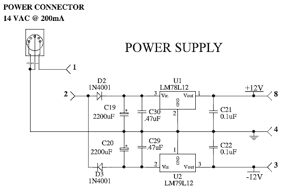
My first experience with split power supply so have mercy. If half wave rectification gives less than 50% of the transformer peak voltage why in this configuration is the voltage so high across the filter capacitors. I expected the board to use much less current than it does and more current flowing in the ground wire. What am I missing?
This is important to me because I want to power my 386 pitch preview amp from the positive regulator, though my board does have its own regulator so I can get power directly off the big cap plus there are pads for another 2200 uf on my second 3 x 3 board if needed. I am aware of T0-92 style heat sinks, cute. There is a tiny bit of warmth on both 12v regulators.
The 5-pin din of the Hot Rodding schematic seems miss numbered?
AC at the plug = 14.9vac unloaded 14.6vac loaded
Across both 2200uf cap = 18.5 vdc
2.1 ma measured on the ground connection.
32.7 ma positve regulator
34.7 ma negative regulator
This latest board uses big radial capacitors on their side, my previous used axial so they do make changes to the PCB more than I thought.


