Let's Design and Build a (simple) Analog Theremin!

Posted: 11/15/2014 1:24:45 PM
FredM

From: Eastleigh, Hampshire, U.K. ................................... Fred Mundell. ................................... Electronics Engineer. (Primarily Analogue) .. CV Synths 1974-1980 .. Theremin developer 2007 to present .. soon to be Developing / Trading as WaveCrafter.com . ...................................

Joined: 12/7/2007

I am really interested in seeing where this goes too..

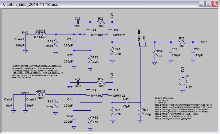
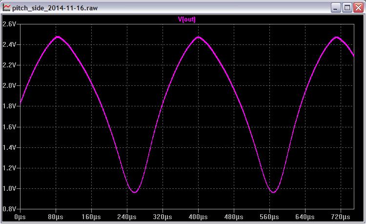
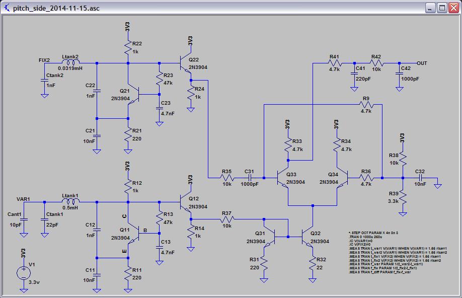
The oscillators (particularly the last) are lovely as high sensitivity oscillators go - Ideal when one needs a large frequency change for small capacitance change (I measured 18kHz/pF on the last!).

To me, the really interesting thing is seeing a completely new approach being explored - an approach which comes from a great primarily digital designer - I have no idea how Dewster is planning to reduce the sensitivity down to the required ~<3kHz/pF for direct-to-audio heterodyning (if this is in fact what he is planning), or how he plans to improve linearity, let alone the convolutions required to do the analogue in 3.3V..

But its this that for me makes this thread interesting.. Lets give Dewster the time to explore his direction - he knows the issues on the table (linearity, sensitivity etc) and must have ideas in his mind to address these - these ideas will either work or they wont.. And if they work we could have something special and have been privileged to have been spectators of the process - And if it falls flat, then we will still learn from this.

The thing which is special to me about this thread is that a designer is doing this process publicly - this is extremely brave IMO, and highly educational for those who follow it - regardless of the outcome.

Those who just want a ready laid out schematic and circuit board will either need to wait and see how this turns out, or go to one of the many available proven designs out there.

Perhaps the word "simple" is the problem - To design a good theremin which is easily constructed with available parts is not simple! - The end result will hopefully be simple to construct and get running, but the process to get to such a thing is no simple matter!

Fred.

Posted: 11/15/2014 5:14:31 PM
dewster

From: Northern NJ, USA

Joined: 2/17/2012

"...so, is it better then osc with the "current mirror"?..  - Alesandro

It does appear to be a better candidate than the previous current mirror Clapp.  This morning I fired up the the oscillator and saw -13ppm drift over 5 minutes from a cold start (no antenna, no enclosure).  With the desk lights off I see <20ns of phase noise, and no jumping or fluttering.  Hooking it up an antenna in my heated room it moves around some - I believe air currents and such are major perturbers of all Theremin oscillators and there isn't a lot you can do about it.

This oscillator makes me think that minimal frequency change with supply voltage change is a good sign of inherent oscillator stability.  Varying the supply from 3.3V down to 2V I see -8ppm change.

...and what's about linearity and sensitivity issues?.."

Since this will be a simple analog LC Theremin with no EQ coils, I hope to show (or not, as the case may be) that heterodyned linearity and sensitivity are invariant and completely independent of oscillator topology.  It's my unproven conjecture that the invariant (if it indeed exists) is often hidden by oscillator coupling in the far field.  But I could be wrong.

Posted: 11/15/2014 6:33:13 PM
dewster

From: Northern NJ, USA

Joined: 2/17/2012

Fred, thanks for (as usual) articulating things much better than I can!  This thread is a total lark and I hope I can do it justice.

Re. sensitivity:

Spicing the latest oscillator I agree with your absolute sensitivity number (I get -15kHz with +1pF).  Adding 1pF to the oscillator on my bench I get 1228.228kHz - 1214.004kHz = 14.224kHz.

Physically seated with my body one arm span away from the oscillator with a 250mm length / 10mm diameter antenna the frequency counter reads 1228.406kHz.  Moving my fist roughly to the midpoint it reads 1227.990kHz which is a difference of -416Hz.  So an imaginary local oscillator set to the first frequency (1228.406kHz) would give 0Hz or null at the far position, and a 416Hz beat tone in the mid field.  Opening my fist at the midpoint the counter reads 1227.688kHz, which would give a beat tone of 718Hz.  718 / 416 = 1.73 or a bit less than an octave for hand closed/open in the mid field.

Next I changed the capacitance in parallel with the antenna from 22pF to 100pF.  For the same three positions of my hand I get 713.507kHz, 713.437kHz, and 713.380kHz, which give imaginary beats (after adjusting the imaginary local oscillator to 713.507kHz) of 70Hz and 127Hz.  127 / 70 = 1.81 which isn't significantly different from the 22pF case, and indeed this is the sort of thing predicted by the invariant. 

Note also that the mid field closed fist beat went from 416Hz to 70Hz, which is a change of log2(416 / 70) = 2.6 or just under 3 octaves, when all I did was roughly quadruple the tank capacitance (and one might naively expect only an octave or so of drop due to f=1/(2*pi*sqrt(L*C)) ).  This larger than expected ~3 octave drop is also something that the invariant predicts (and dramatically increases the effect of capacitive padding e.g. employing small antenna length changes for tuning purposes - and that tuner on the Melodia must be really squirrely).

The above single points don't prove anything, nor do they address linearity.  I guess we'll see where all this goes.  I'm hopeful that it will work out and give people a real alternative to the standard EQ coil type designs out there which can be notoriously difficult to tune.  The SC / Jaycar works this way (i.e. gargantuan tank C padding and no EQ L) so nothing really new is happening here in terms of fundamental operation.

Posted: 11/15/2014 7:33:30 PM
dewster

From: Northern NJ, USA

Joined: 2/17/2012

Oscillator Swing

One thing that's really nice about having an EQ coil is that it boosts the tank voltage.  Following this back it also gives you a lower voltage tank swing - so if you simply make a copy of your variable oscillator and use it as your local oscillator you get two similar swings that are easy to mix, and the lower voltage swing of the local oscillator isn't spraying all over the place and causing unwanted coupling.  And what can be easier than copying?

This scenario is actually pretty easy to replicate with no EQ coil when using the Theremin adapted Clapp or Colpitts oscillators.  These employ split capacitors to jack up the voltage when you want to do so (for the variable oscillator) or not (for the local oscillator).  The only possible issue is inductor sizing - you may need to use a smaller inductor with larger capacitors in the lower swing oscillator to get the same frequency as the larger swing oscillator.  But if you tap off of the same drive point you will get roughly equivalent swings for mixing.

Posted: 11/15/2014 7:49:50 PM
tinkeringdude

From: Germany

Joined: 8/30/2014

"...so, is it better then osc with the "current mirror"?..  - Alesandro

Hooking it up an antenna in my heated room it moves around some - I believe air currents and such are major perturbers of all Theremin oscillators and there isn't a lot you can do about it.

Maybe stupid question from me n00b here, but aren't these current mirrors not used in those kind of circuits to make things less temperature dependent, by having the changing characteristics of a transistor cancel out by another transistor which is more or less thermally coupled? (maybe it wasn't a current mirror but other sort of 2-transistor circuit, I faintly remember some talk about VCAs where it was explained like that... sorta)

Posted: 11/15/2014 7:59:04 PM
dewster

From: Northern NJ, USA

Joined: 2/17/2012

"...aren't these current mirrors not used in those kind of circuits to make things less temperature dependent, by having the changing characteristics of a transistor cancel out by another transistor which is more or less thermally coupled? (maybe it wasn't a current mirror but other sort of 2-transistor circuit, I faintly remember some talk about VCAs where it was explained like that... sorta)"  - tinkeringdude

Yes, and a good reason (among others) when using discrete transistors to keep the transistor count in the oscillator itself to a minimum.  Though I believe the degeneration resistors in the current mirror emitter leads tend to make things less temperature sensitive than they otherwise might be.  VCAs can use the exponential transfer function of a transistor, and this is highly temperature sensitive.

The thermal issues I see most are I believe due to the fluctuating electrical properties of the air itself as the warm streams waft past the antenna (my bench is located over the intersection of two baseboard radiators).

Posted: 11/15/2014 8:25:58 PM
tinkeringdude

From: Germany

Joined: 8/30/2014

"The thermal issues I see most are I believe due to the fluctuating electrical properties of the air itself as the warm streams waft past the antenna (my bench is located over the intersection of two baseboard radiators)." -- dewster

Ah - you mean the property of the "air as dielectric" changes with temperature and hence the capacitance? Since e.g. the density changes. I wouldn't have guessed that the differences as are drastical

Posted: 11/15/2014 9:13:14 PM
dewster

From: Northern NJ, USA

Joined: 2/17/2012

"Ah - you mean the property of the "air as dielectric" changes with temperature and hence the capacitance? Since e.g. the density changes. I wouldn't have guessed that the differences as are drastical"  - tinkeringdude

Yes.  When you're resolving down to attofarads, all of the monsters show up to play.

Posted: 11/16/2014 8:18:56 PM
dewster

From: Northern NJ, USA

Joined: 2/17/2012

Pitch Side

I feel kind of weird shoving somewhat inferior NPN oscillators on people, and the FET Clapp is a thing of beauty, so I'll be switching to that in this thread, probably for good.  FETs also come in handy for simple transmission gate sample & hold type mixing.

Above are two FET Clapp oscillators, each with their own FET buffer stages.  The fixed oscillator on the top has the inductor adjusted to give a 3.1kHz beat tone.  Antenna amplitude is 40Vp-p in the sim, fixed tank amplitude is about 8Vp-p.  The variable oscillator drives the gate of another FET which acts like a sample & hold for the output of the fixed oscillator, and the result is filtered with a droopy 2nd order LPF.  This kind of sample & hold is actually like boxcar filtering, which tends to smooth out the waveform.

Above is the result of mixing and filtering in the sim.  The output is a fairly healthy 1.5Vp-p.

I need to buy some FETs (I only have 3) and get this running on the bench.

LTSpice file: http://www.mediafire.com/download/enpm8nmnbckyv5r/pitch_side_2014-11-16.asc

Posted: 11/16/2014 8:35:33 PM
dewster

From: Northern NJ, USA

Joined: 2/17/2012

Dead End?

Was working on this sim yesterday and today:

It uses two common base Clapps and a variable gain differential pair with current mirror biasing to do the mixing.  In simulation it gives a nice looking 1Vp-p ~sine wave at the output.  Lots of transistors!

LPSpice file: http://www.mediafire.com/download/6c6hrrpn2jutkoa/pitch_side_2014-11-15.asc

You must be logged in to post a reply. Please log in or register for a new account.