Enhancing The EtherWave Sound

Posted: 3/10/2016 3:25:11 AM
oldtemecula

From: 60 Miles North of San Diego, CA

Joined: 10/1/2014

Hello dewster,

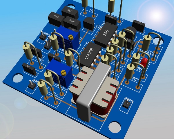
The 555 only drives the LED which indicates the signal level is high enough to create the sound and it can be a Null indicator. A transistor drives the 555 and the audio transformer, I seem to be doing some sort of phase shifting. I am clarifying the schematic which I will post soon, the 3D image is created from this. Not seen is an Opto LED switching on a NPN photo transistor (V0618A) which is the part I do not know how to create.  Autotrax in England will create the part for me for $10 which I might buy. Do you think the sound is interesting? Once I post a schematic hopefully you and others might suggest things to try before I get a few PCB's made.

Happy Birthday My lovely Clara

Christopher

Posted: 3/11/2016 7:15:52 PM
oldtemecula

From: 60 Miles North of San Diego, CA

Joined: 10/1/2014

Not too much TW response, I hope my research is not another mindless delusion. The new PCB software I am using makes me want to adventure further as it is fun to use. I have never worked in electronics so have a few questions on PCB fundamentals, what thickness is one ounce copper, what is best for DIY soldering, minimun track width of .02" looks good on the layout. The EWS board copper is like paper and the foil tracks easily self destruct. I also need to verify my pad and drill hole sizes.

The board ends up under 3" x 3" in size using an extra middle track layer.  It fits nicely in the volume side of the EWS enclosure using a 4 pin ribbon between the two boards. This cable being un-shielded has me a little concerned 50/60 hz hum and using a 8" ribbon length (20cm).

I need to study the other features mentioned and how to implement them. Still need to draw up the smaller breakout PCB board, this is where all the features begin.

Christopher

Posted: 3/11/2016 10:25:32 PM
dewster

From: Northern NJ, USA

Joined: 2/17/2012

"Not too much TW response..." - Christopher

I think everyone is stuck in that tar pit of social engineering known as Facebook.

Posted: 3/12/2016 2:19:16 AM
oldtemecula

From: 60 Miles North of San Diego, CA

Joined: 10/1/2014

dewster you passed the test!  Actually found two other resistor values that were upgraded from the original design. Grounded pin 1 and noticed my software will eventually output a Spice file but not yet.

Need to use Pot-R17 on the input as the board could help any line level theremin sound. The 100k / 1uf combo gives me the low freq response. I will reduce the Op divider resistors from 100k to 10k.

Christopher

Posted: 3/12/2016 11:37:56 AM
dewster

From: Northern NJ, USA

Joined: 2/17/2012

Christopher, I'm not saying there's anything wrong with your circuit, everyone has their own style, but I'd maybe go for more gain in the first stage and less in the second, or eliminate the second altogether.  I'd roll off HF in the first stage as well, via capacitance to ground in addition to capacitance across the feedback - kill anything problematic (ultrasonic and RF) before it can get in and cause trouble.  If you don't need the gain to go all the way to zero you might try making the feedback R variable, as this scales noise with gain.  The VCC/2 divider should probably have a decoupling cap to ground.  It looks like your pots have DC across them, which is something I generally try to avoid.  I'd maybe try to remove some of the load from the second opamp.  And it doesn't seem the opto-isolator is necessary?  There's no noise coupling, level shift, HV, or shock hazard issue there, so I'd play around with just driving the gate of a regular NPN, and work extra hard to get rid of any specialty items like that.

If you haven't read the books by Douglas Self they're a treasure trove of audio circuit design.  And there's a new version of "The Art of Electronics" out now that is the bible.  Self's books and "The Art" are both super readable and surprisingly entertaining.

Posted: 3/12/2016 2:34:30 PM
oldtemecula

From: 60 Miles North of San Diego, CA

Joined: 10/1/2014

Tomdog likes the sound trick but with no other input from other musicians I can not be sure the circuit does anything?

dewster said: "I'm not saying there's anything wrong with your circuit, everyone has their own style, but I'd maybe go for more gain in the first stage and less in the second, or eliminate the second altogether."

How do you like the Verizon switch over to AOL?

This is the beginning of a path for discussion as I was never the brightest bulb in the room. I will create a webpage as I always do to gather and organise the input from anyone.

The opto-isolator is the trick, the internal LED is audio modulated and reverses the signal direction to the transformer. A transistor would need testing here but I think more is involved.

Manipulating sound is very subtle and I don't think sound can be captured in spice modeling which by my understanding just tells you how good a circuit is working electrically? I have never tried Spice, probably too old to learn and then again I am amazed how easy modern circuit board layout has become. I did come out of retirement but only for a moment.

The above image is the re-design in process using new PCB software.


Christopher

Posted: 3/13/2016 5:05:35 AM
senior_falcon

Joined: 10/23/2014

"Not too much TW response, I hope my research is not another mindless delusion. Christopher"

Hi Christopher - It's hard to respond without knowing more about what you are working on.  I would be interested in a DIY project that changes the sound of the Etherwave into something more like the tube theremins, especially in the higher registers, provided the board would fit neatly within the EW case.  I have Thierry's ESPE module and like the way it softens up the sound of the etherwave - would this be compatible with your board?


Posted: 3/13/2016 5:24:13 AM
oldtemecula

From: 60 Miles North of San Diego, CA

Joined: 10/1/2014

Falcon said: " I would be interested in a DIY project that changes the sound of the EtherWave Standard into something more like the tube theremins, especially in the higher registers, provided the board would fit neatly within the EW case."

Yes my project fulfills all of the above if the sound is acceptable as it is now. I posted this sound byte for analysis which is theremin direct to sound card. No processing, reverb or anything extra done. I think it improves the EWS sound by just dampening the third harmonic but if the musicians do not agree then I shall go back into my retirement. I have been writing computer code to play the stock market the last six months and I am ahead of the game, not by much but that is a win in this market. My being a 50 year electronic hobbyist surely makes me seem a little crazy. 

The developing new sound of the EtherWave Standard can be found on my website.

Christopher

Posted: 3/13/2016 6:05:24 PM
dewster

From: Northern NJ, USA

Joined: 2/17/2012

Christopher, LTSpice is about as easy as it comes, I highly encourage you to play with it a bit because it can quickly make one a better designer.  Circuit simulation isn't the be all and end all, and it can often give incorrect results (particularly with high Q oscillators and such) but I don't know of any other way to mentally "take in" circuits that are non-trivial.  Even one transistor can stymie my poor brain.  Spice is great for examining currents, which are difficult if not impossible to measure in-circuit.  You don't always have to spice the entire enchilada to gain intuition.  I find a combination of Spice and breadboarding yields the best results for me as the two processes provide mutual reality checks on each other.  Once you get the hang of it, simulation is usually much easier to do "what if?" kinds of exploration than with actual hardware.

Posted: 3/31/2016 3:36:42 PM
oldtemecula

From: 60 Miles North of San Diego, CA

Joined: 10/1/2014

dewster said: " LTSpice is about as easy as it comes, I highly encourage you to play with it a bit because it can quickly make one a better designer."

I did download it but the grayness & graphics seemed clunky, I am sure it works for complicated stuff like precise digital but I am only doing basic analog circuits where ohms law and 5% accuracy of a slide-rule gives me answers.

In my sample below I almost completely attenuate the 3rd & 6th harmonic for a nice theremin sound coming from an internal modification to an EtherWave Standard. I think relying on modeling would have kept the method hidden from me as I would never have had hands on much less made anything physical. I think Thierry calls it the difference between theory and practice.

The sound of adjustable harmonic control of the theremin. sound.wav     <= no puny whistle - theremin direct to sound card.

Observe the harmonic distribution on software, it is interesting and mathematical.

Christopher

You must be logged in to post a reply. Please log in or register for a new account.