New Vacuum Tube Theremin Design

Posted: 3/9/2017 1:00:39 AM
markaudiomusic

From: Canada

Joined: 3/9/2017

Hi all,

PLEASE CHECK MY WEBSITE FOR LATEST CHANGES, INFO, AND SAMPLES ON MY DESIGN.

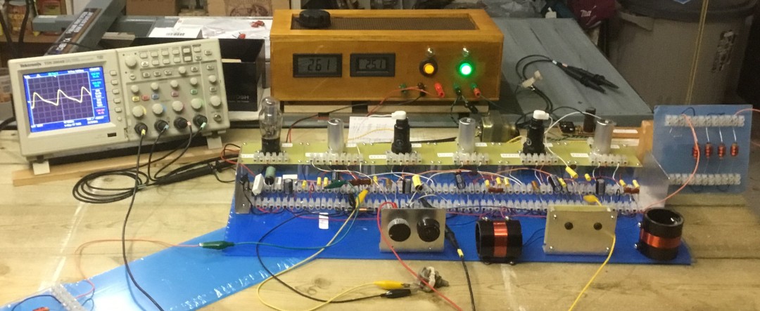
I have breadboarded a new (for me) vacuum tube design. It works very well - This website (not commercial) https://markaudiomusic.com/ shows the schematic and design logic and some sound samples. I would appreciate comments, suggestions and criticisms.

It was fun designing the theremin from first principles. The next task is to transfer the design to a chassis. I know many parameters will change. I will update as the project progresses.

Cheers,

Mark

Posted: 3/9/2017 7:29:07 PM
oldtemecula

From: 60 Miles North of San Diego, CA

Joined: 10/1/2014

Mark you got skills!

Your write-up is detailed and enjoyable. I miss the old style of theremin design, they have the warmth like the shortwave radios back in the 50's.

Age is taking its toll on me but visit this webpage where I give my interpretation of what creates the fat theremin sound. You are correct it is all about waveshape and Lev Sergeyevich did it without a scope.  It always seemed to me the vacuum tube has a slower roll-over of the wave which gives the best fat sound. I also share sound samples.

Visit the Henk Brand pages, he is awesome.

Thank you for demonstrating your sound, it shows me you have advanced beyond just talking.

Christopher

Posted: 3/9/2017 8:07:03 PM
dewster

From: Northern NJ, USA

Joined: 2/17/2012

Mark, you might want to lift those air coils off of your wooden bench by at least 1".  I recommend a plastic spacer of some sort.  Heck, lift the entire thing up a couple of inches.  Wood isn't entirely blameless when it comes to capacitance.  I'd mount the antennas on something plastic too, rather than wood.

Your write-up is nice and I pretty much agree with it.  I think one of the big mysteries when technical people are trying to figure out the Theremin is the inductance in series with the antenna.  Thierry explains it via mathematics, but I like to look at it as the main or dominant LC tank, stimulated by and influencing resonance of the oscillator LC tank, with the relative tuning between them altering the shape of the heterodyned pitch response.  I don't like this topology because I find it very difficult to tune, and believe the best tuning would be a variable C antenna pad (fairly squirrelly due to the 3x effect on heterodyned pitch) along with a second tuning control for the fixed oscillator.  Or, somewhat equivalently, have tuning controls for both the fixed and variable oscillators on the front panel (perhaps one knob that alters both, and another that changes the ratio between them, kind of like volume and balance).  That way the user could compensate for a variety of intrinsic C playing environments.

The article you point to (http://www.dogstar.dantimax.dk/theremin/thersens.htm) is perhaps misleading.  For a simple Theremin (without the series inductance) tuned so that there is a far-field null, I don't believe one can do anything to alter the basic musical sensitivity (in terms of octaves of response).  Capacitive padding at the antenna will lower absolute sensitivity, but musically will only lower the overall pitch.  This is easy to understand mathematically: the ear perceives pitch logarithmically, so we need to feed it an exponentially based pitch in order to hear a linear sounding response.  Multiplying in the exponential domain (changing the absolute sensitivity) is the same as adding in the logarithmic domain (changing the relative pitch).  That article doesn't even discuss the log pitch response of the ear, which is a critical omission.  I've dubbed this inability to alter the musical sensitivity the "invariant" and I believe it is why you don't see any linear analog Theremins with, say, a 2 octave range (or something more playable than the standard 6 or so octaves).

Have you experimented at all with mains hum reduction?  I've found a simple resistor (100k to 1Meg) from antenna to ground acts as an RC with the intrinsic C of the antenna, providing a lot of low cut at mains frequencies.  It's also a Q killer, so I tend to avoid using it, but may experiment with adding a fairly high value here in the future.

I think you should emphasize the positive aspects of oscillator decoupling in your article.  Coupling can give a richer waveform in the lower octave, and can give a silent instrument if left alone, but at the expense of an even more non-linear playing response down there.  I don't think the trade-off is worth it.
Posted: 3/9/2017 9:40:14 PM
markaudiomusic

From: Canada

Joined: 3/9/2017

Thanks Chris for your kind comments. I love your sound. Very rich. Much nicer than mine.  I will keep working on the tone.


dewster: Thanks as well for your thoughts. I think I will remove the link to the article you mentioned.

I will lift the whole thing up a few inches and check the response before I commit to the chassis wiring. Thanks. Good point.

Tuning the antenna is a pain. I would like to replace the mini-coils with a hand wound version, but I need to get the inductance value pinned down, and that won't occur until I build it up, and even then, it won't be accurate. Getting then Q of the circuit high really helps the range.

As a musician, I am aware of the logarythmic 'distance' response of any non keyboard instrument. I am, however, new to the theremin field. Do people here expect or want the octave distances to be the same? I like and prefer the short distance in the high end and long distance in the low end. Just like a violin or guitar. 

I haven't dealt yet with hum reduction. I will test your idea.

The breadboard version obviously has a huge amount of coupling. I intend to use rf shields (double sided copper PC board inside the chassis) and standard shields on top.

Is my approach to volume unusual? I haven't come my particular solution. 


Thanks all,

Mark


Posted: 3/9/2017 10:11:43 PM
dewster

From: Northern NJ, USA

Joined: 2/17/2012

Mark, I didn't mean overall undesirable coupling between modules, but coupling between the variable and fixed oscillators on the pitch side.  Your oscillators are buffered before the mixer, and the heterodyned result seems to go down to 2Hz, so there probably isn't a lot of coupling going on.

I believe most Theremin players value a linear pitch field, and the series inductor can make the near-field more linear if you size it correctly.  Thierry may be able to help you size the coil values using math.  Have you tried laying an unconnected scope probe a few inches away from the pitch antenna (perhaps clipped to a few inches of wire) and tuning for maximum voltage swing, then adjusting the fixed oscillator for far field null (then tweaking)?

I can't comment on your volume side as I have very little experience with that side of things.  Though players probably want that fairly linear seeming too (and the ear's response to volume is also logarithmic).

That sensitivity article is really misleading IMO, so it's probably best that you're removing the reference to it.

Posted: 3/9/2017 11:14:21 PM
markaudiomusic

From: Canada

Joined: 3/9/2017

dewster, I lifted the breadboard and antennae off the wood using 1L yoghurt containers. Big difference. Thankyou. I had to add another 2.5mH to the loading coil, which drops the resonant freq of the antenna circuit 10kHz to about 265kHz. I had to drop my oscillators to about 268Hz to get a good response. The field is now nearly linear and a solid 4+ octaves. I am surprised, and I admit, a little pleased. It is much easier to play a piece (I played your National Anthem) when you know the distances are mainly constant.

I have the volume control set up to be more sensitive as you get closer to the antenna. This allows me to easily play repeated notes and staccato.

The sensitivity article is removed.

Posted: 3/10/2017 12:16:46 AM
dewster

From: Northern NJ, USA

Joined: 2/17/2012

Mark, if the whole thing is going to end up in a wooden cabinet then that's probably how you should design and adjust things. Outside of unvarnished wood changing a bit due to humidty, and the difficulty of adjustments going somewhat awry when the case is closed, there isn't anything intrinsically wrong with a wooden enclosure.  It definitely adds C, particularly when placed within a few inches of air coils, and also when the antenna is mounted right in the wood, but even this can generally be compensated for if needed.  I believe anything that doesn't kill Q can generally be compensated for (in an analog Theremin).

So if it's going in a case, build that, stick it in there, and adjust values to restore free-space behavior.

I agree with the part of your write-up that recommends the series coils be aligned with and located near the antennas, particularly if they are air core coils.  The "business end" of an air core is just as sensitive as the antenna itself - indeed there is a "sensitivity gradient" to hand C from the antenna end of the coil (max) to the driven end of the coil (minimum, pretty much zero).  It's interesting to run a finger from one end of the coil to the other, it makes for a kind of touch sensitive playing surface.

Posted: 3/31/2017 11:56:43 PM
markaudiomusic

From: Canada

Joined: 3/9/2017

Hi all,


I have finished my vacuum tube theremin design. It is ready to be committed to a chassis. I have made many changes to the basic design - adding a variable cap coupling tone control, working with more pure sine waves in the oscillators, and simplifyling the power requirements.

The linearizing coils were found to be a basis for frequency determination as the smallest coils a available to me are 2.5mH. This means at least a 4 to 5 kHz jump in resonant frequency. It is much, much easier to create an oscillator that is close to the antenna/linearizing  resonant frequency than it is to match the antenna to a pre-existing oscillator frequency. 

I now have a theremin with one tone control, affect the mixing operation only, that produces a beautiful flute-like sound through to a lovely buzzing cello-like sound.  I will provide some samples in the next few days.

On my website I have made the changes in design noted by coloured text along with the most recent schematic.

Dynamic range is an interesting topic. There is no need of a dynamic range range greater than 30-40dB if one is attempting to have an instrument that stands up against exitsting strings or woodwinds or brass.


Cheers,


Mark

Posted: 4/3/2017 3:26:39 PM
markaudiomusic

From: Canada

Joined: 3/9/2017

THIS IS NOT THE FINAL DESIGN. THE FINAL DESIGN IS 2.8 FOUND ON MY WEBPAGE: https://markaudiomusic.com/

Vacuum Tube Theremin

I have posted sound samples, on my website on the the theremin page, of four different tones obtained from the mixing tone control as well as a sample of repeated notes created by touching the volume antenna.

Cheers, 

Mark


Posted: 4/3/2017 5:19:24 PM
ILYA

From: Theremin Motherland

Joined: 11/13/2005

Mark
I pretty like your crossings-free schematic.

Just one question: why the gas discharge regulator, not a solid?

You must be logged in to post a reply. Please log in or register for a new account.