Yet another "extending the range of a theremin" thread

Posted: 6/5/2017 10:54:06 AM
carebare47

Joined: 6/1/2017

The negative output of the function generator should be earth grounded, as should the negative input to the scope probes (scope probes are usually grounded to the AC outlet ground, which is an earth ground, but function generator outputs are often floating).  You should also be using a good quality RF choke here or an air-core hand wound single layer solenoid.  If you do these things, believe me, you'll know when you hit resonance!  Resonance can be quite narrow for a high Q coil, and it's probably easiest to locate using sine wave drive from the function generator.  A small resistor (~1meg or so) from the antenna scope probe to ground can help kill hum."

I've always assumed the negative clip on the scope was earthed, and so I did connect that to the negative clip from the Fgen. Didn't have any proper fgen leads so I used another scope probe, didn't think of it at the time but could the capacitance of the output probe from the fgen be pulling the resonance off? 

Guessing a plate to person capacitance of 3pF (is this a sane ballpark guess?), this means I should be aiming for a 8.44mH inductance at 1MHz right? (1/(2*PI*F*sqrt(C)))^2. 

This is the inductor I used: http://uk.rs-online.com/web/p/leaded-inductors/8004381/?searchTerm=800-4381&relevancy-data=636F3D3126696E3D4931384E525353746F636B4E756D626572266C753D656E266D6D3D6D61746368616C6C26706D3D5E285C647B362C377D5B4161426250705D297C285C647B337D5B5C732D2F255C2E2C5D5C647B332C347D5B4161426250705D3F292426706F3D3126736E3D592673743D52535F53544F434B5F4E554D4245522677633D4E4F4E45267573743D3830302D34333831267374613D3830303433383126

Do you think that winding my own for about 8.5mH will provide significantly different results? Is this due to the air core that I would use? 

I'll give the resistor a go too.


I've been running LTSpice sims (Thanks for the inspiration Buggins, finally taken the dive and had a go at LT, fantastic bit of software!) and from what I can tell I can increase the range/sensitivity of the strange apparatus theremin significantly by changing some values. I'm going to go and hang cutlery out of a tree once the weather clears up and see how well it works in the real world. 


Thanks for all the help so far everyone!


Edit: when y'all talk about winding single layer inductors, do you mean a pancake or a single-walled cylinder? 

Posted: 6/5/2017 6:31:49 PM
dewster

From: Northern NJ, USA

Joined: 2/17/2012

"I've always assumed the negative clip on the scope was earthed, and so I did connect that to the negative clip from the Fgen."

It's probably grounded.  You can check the resistance between the scope probe ground and AC ground with a DMM.

"Didn't have any proper fgen leads so I used another scope probe, didn't think of it at the time but could the capacitance of the output probe from the fgen be pulling the resonance off?"

If that's a 10x scope probe then the resistive divider inside is massively killing the drive.

"Guessing a plate to person capacitance of 3pF (is this a sane ballpark guess?), this means I should be aiming for a 8.44mH inductance at 1MHz right? (1/(2*PI*F*sqrt(C)))^2."

The intrinsic C of the antenna will be the biggest C factor.  Around 10pF for a normal Theremin antenna, more for one with a larger surface area.  Plus whatever C you are doing the sensing through.  Once you find the frequency at which it resonances you will be able to work backwards to the intrinsic C value of the antenna.

"This is the inductor I used:..."

That's most likely a very poor inductor to use for this application, the self-C is probably higher than the antenna intrinsic C, which will kill series resonance.  I tried a bunch of different inductors like those (from my junk box) and only one or two would work at all (i.e. resonate when in series with a small C).

"Do you think that winding my own for about 8.5mH will provide significantly different results?"

Yes, wind your own, or at least use the type of RF choke used for Theremin series EQ (Bourns 6300 series).

"Is this due to the air core that I would use?"

Air core will give you the highest Q, the lowest self-C, and the best thermal stability.  They can be physically rather large however.

"Edit: when y'all talk about winding single layer inductors, do you mean a pancake or a single-walled cylinder?"

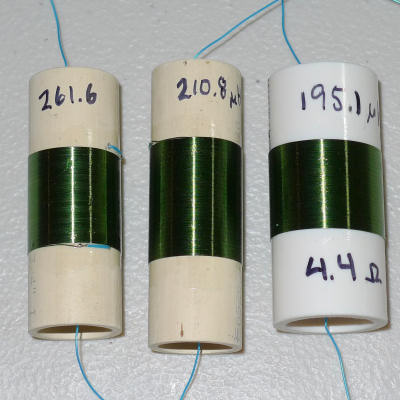
Single walled cylinder (a single layer solenoid, where the turns of wire are adjacent to each other and don't overlap in any way). Here are some of my older smaller coils wound on PVC pipe:

These days my coils are somewhat larger and higher in value.  The pitch side is currently 2mH, the volume side is ~4mH.

You want an aspect ratio of roughly 1:1 (height to diameter) as this provides a balance between highest interwinding coupling (closer windings = higher coupling = shorter wire length = lower DCR = higher Q) and lowest self capacitance. 

You should use a fine wire that you can easily handle, I recommend 32 or 34 AWG.  Get the enamel single coat stuff that the outer insulation melts with a soldering iron - this makes it easier to attach the leads (I use wire wrap wire here).  Drill small holes for the leads at each end before you wind, this gives a sanity check as well.  Fix things with clear nail polish.  For one-offs you could conceivably just wind them by hand, but I find a simple hand cranked jig makes things a whole lot faster and easier.  And PVC knockout plugs make great coil mounts.

You must be logged in to post a reply. Please log in or register for a new account.