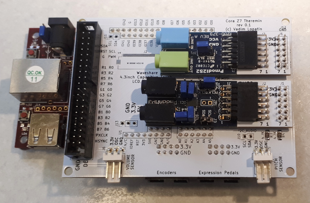
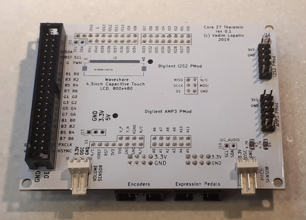
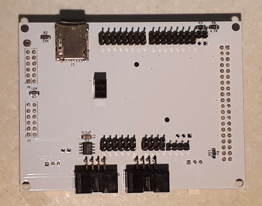
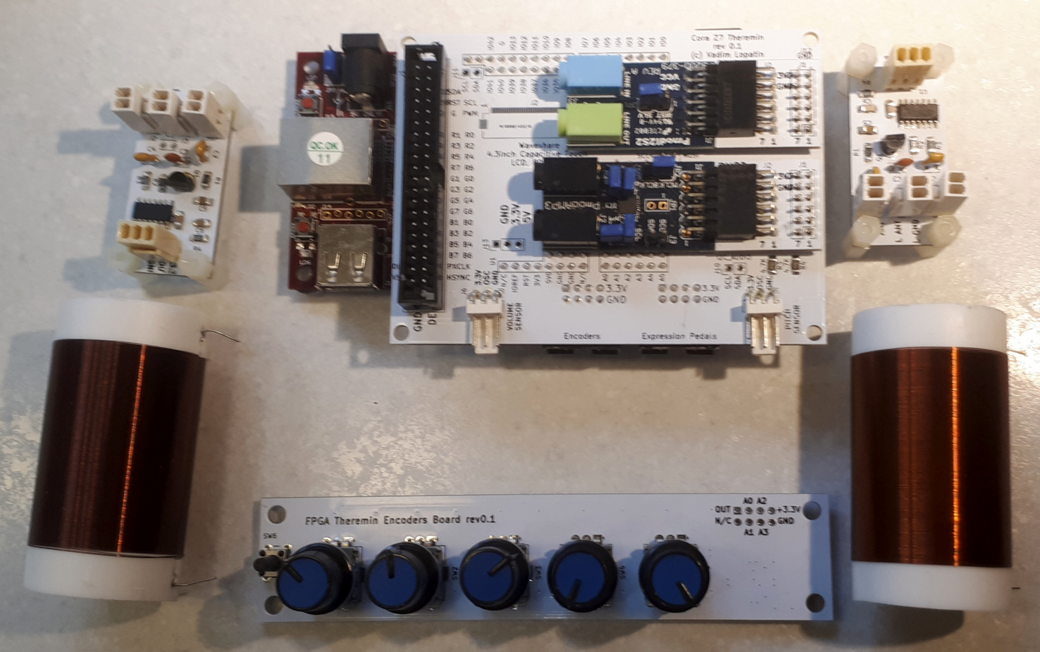
Project update:
Completely rewritten / redesigned theremin sensor module. Now it's completely in SystemVerilog.
Pitch and volume signal period measure and IIR filter.
Source code is available on GitHub
Contains Xilinx (Series7) specific resources usage.
Both Pitch and Volume frequency measure use DDR deserializer with x8 oversampling based on delay primitives.
Single channel of signal period measurement uses ISERDESE2 on 600MHz (150MHz output) deserializer working in DDR mode (gives 600MHz*2 = 1.2GHz measurement precision). Oversampling deserializer uses 8 such channels with inputs fed with original signal delayed by different delays. Output is 64 bit parallel deserialized value avalable each 150MHz cycle. Precision is equivalent of 1.2GHz * 8 = 9.6GHz counter.
Parallel 64 bits are converted to change flag and changed bit number.
On next step, flag and bit number are used to accumulate unchanged value period duration. Output is duration since last change (in 9.6GHz ticks) and change flag.
Next step: convert sequence of half-periods to periods (two recent half-periods give time interval since the same edge of signal). This is needed for proper support of non-50% duty cycle signals). As well it adds one more bit of output result.
Output of period measure gives 14-16 bits of signal (depending on source signal frequency).
Double channel IIR filter with configurable number of stages (4 by default) and 1/2^k coefficients implements averaging and increases number of available bits. 8 bit right shift is now used as filter K.
Each 100MHz/2/4 = 12.5 MHz cycle, new value of pitch and volume IIR filter outputs is available.
Output is now configured to provide 28 bits of data.
This design in current configuration (both volume and pitch have x8 oversampling, 28 output bits) utilizes <400 LUTs (<2% of available resources).
Next steps to do in Theremin Sensor implementation:
1) Scaling - output of IIR filter should be converted to desired range (normalized) - (value_in - min)*out_range/(max-min)
2) Linearization - non-linear input from previous stage should be converted to linear distance
3) Distance to note, note to frequency (phase increment)
4) Distance to volume
So far, I'm unsure what is better approach - table based approximation or some program for soft core inside sensor.
If soft CPU selected for controller extension, it can replace IIR filter (which uses 100LUTs). One or two threads of CPU may work as IIR for sensor data.


