Replicating the Antenna Equalizing Inductors
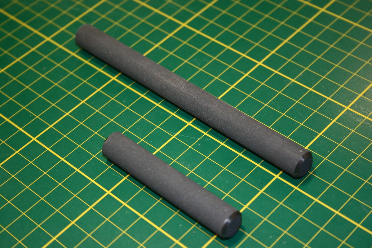
I was able to buy 1/2" ferrite cores in 4" and 8" lengths. These needed to be cut shorter for the Melodia, and for some reason I thought that the material would be easier to cut than it turned out to be. On some smaller (and cheaper) rods I tried making dry-cuts with several different diamond wheels, but the material would chip terribly. I finally read somewhere that heating would cause fracturing, so I dug out my tile wet-saw. Even bathed in water the rod would randomly decide to fracture and ruin the cut.
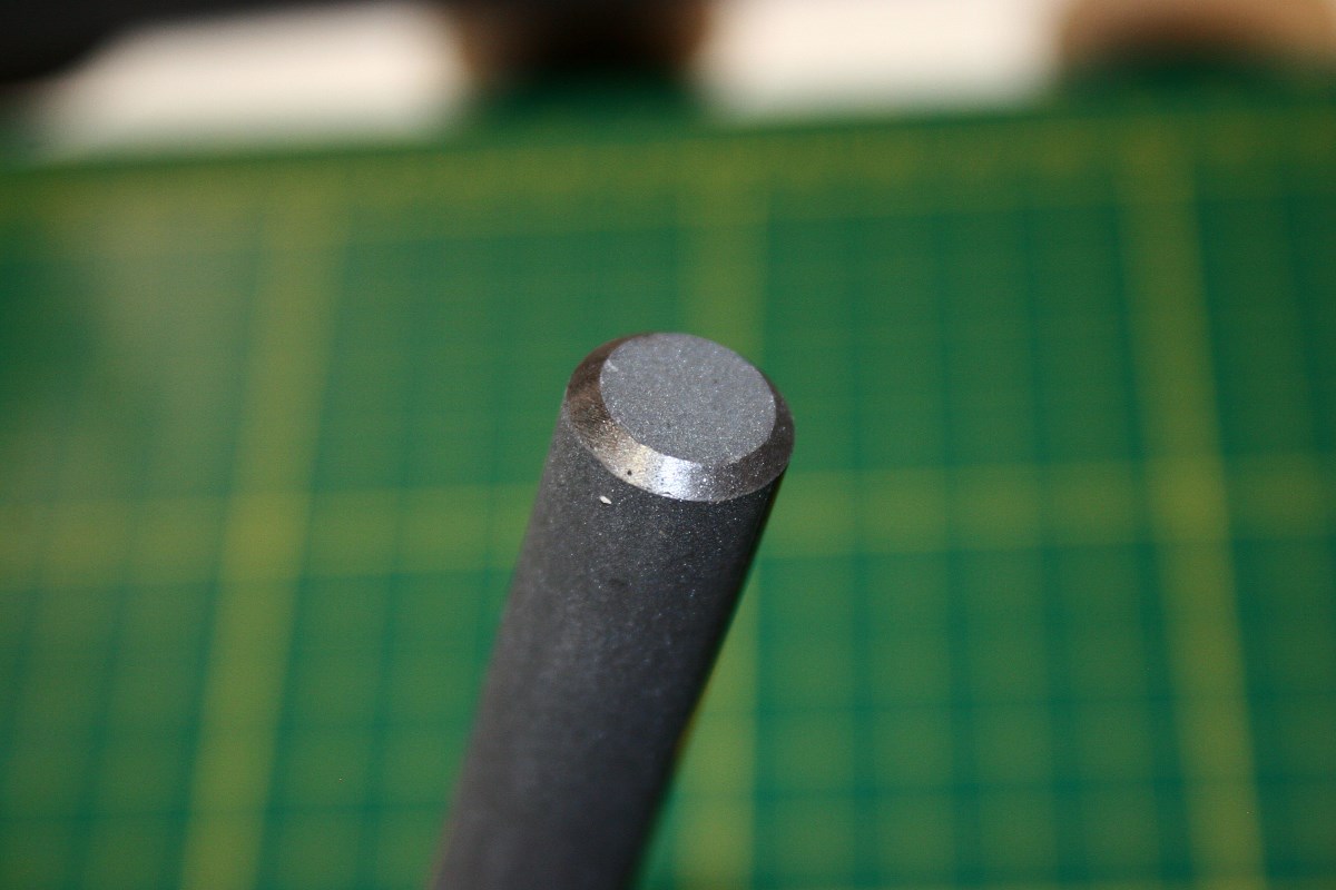
I finally made a wood support block with a 1/2" diameter cove routed into it to fully support the rod right up to the cut line. Even with this the rod would chip around the cut line, but I went ahead and cut the rods close to length and end-ground them to final length. Any remaining chipping was hidden by bevel-polishing the ends. Whew - I'm glad that's done.
Winding the Inductors
This is probably going to be the biggest challenge of the project. The goal here is to not only make a machine capable of replicating the simple "Universal" wind used on the four variable inductors/transformers (and the multi-section coils used in the Etherwave), but also one that is capable of applying the more complex "Progressive-Universal" winding used on the Melodia's large antenna inductors.
A universal coil winder would be easy to make in a few hours. Dave Gingery wrote a booklet describing the construction of a winder that was essentially the same as the old Morris Coilmaster winder that was sold in the 1960s.
Morris Coilmaster:

A Gingery Version of the Coilmaster:
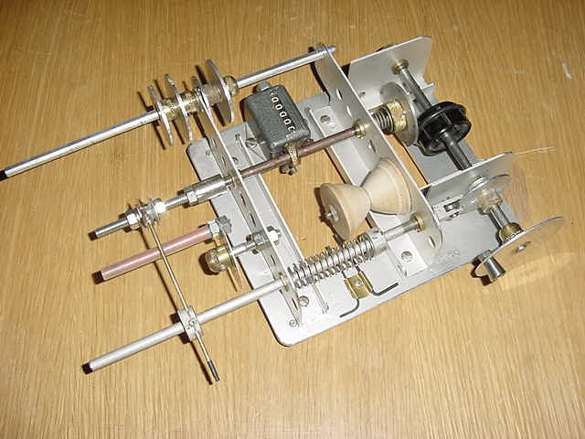
A core spindle is rotated while a wire guide moves laterally to wind the wire in a helix pattern, thereby minimizing inter-winding capacitance. The lateral movement is not exactly synchronized in a 1:1 ratio to the spindle rotation in order to prevent the wire from winding directly on itself. The Morris machine uses selectable gearing to lock spindle rotation to lateral movement; the Gingery knock-off uses a continuously variable rubber-tire/disk transmission that also serves to provide the required right-angle translation without the need for bevel gears.
Both winders have a few points that could be improved upon. It would be slightly better to have the spindle drive (which can slip under wire tension) linked directly to the crank handle, with the variable transmission driving the cam that provides the lateral movement. Secondly, the lateral motion should ideally be linear, provided by a cardioid-shaped cam rather than a circular disk with an offset center. And finally, introducing a pair of linked arms (adjustable) into the fixed linear motion of the cam follower would provide a continuously adjustable lateral movement, allowing coils of different widths to be created without the need for using multiple interchangeable cams.
A Progressive-Universal winding machine is considerably more complex. In addition to the fast cyclical lateral movement (on the order of the spindle rotation rate) of the wire guide, a slow lateral translation is introduced to shift the spindle continously as the helical windings accumulate. This results in an inductor that can be thought of as similar to a multi-section pi-wound choke (such as the 3-section coils used in the Etherwave) except that the coil is wound continuously rather than separated into discrete sections. Here is a patent for such a machine (provided to me by a helpful contributor on the EEVBlog forum):
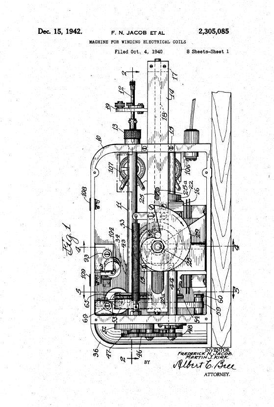
From what I can determine by reading the patent (always a joy...), the large central cam in the above picture is driven by a right-angle worm gear and provides the slow translation of the wire guide support arm. The faster lateral movement to create the helix wind is provided by the wire guide sliding within the support arm at a rate determined by an end-driven cam follower which is geared to the spindle rotation.
All in all this is an interesting but painfully complex machine to replicate, and one that requires multiple gearing and cam options to be versatile.
So what to do?
A simple mechanical helical Universal winding machine is easy to build, although an electronically programmable machine using a microcontroller and stepper motors may be just as easy for some. But the introduction of the need for lateral translation to achieve a progressive-universal wind makes an electronic version the only practical choice.
So the options I am considering are as follows, and unfortunately none of these are quick or easy. I don't like projects within projects, but from the start of the Melodia effort I was committed to making an effort to reasonable replicate the inductor windings as well.
Option 1
I have two metal lathe options - one medium-sized lathe that can provide a lead-screw translation motion geared to the spindle, and a small Taig lathe that can provide a slow open-loop translation that is not tied to the spindle. For either of these lathes I could make a spindle encoder wheel to measure angular spindle rotation, and use a micro to convert this to drive an RC servo to shift a wire guide (for the helix wind), while letting the lathe's lead-screw provide the translation. I don't think the translation needs to be locked to the spindle rotation unless you need to be able to stop and back up during the winding process.
Option 2
Make a dedicated dual stepper winder. This would end up looking a little like a lathe (which is why I would like to leverage one that I already have). The spindle however would be driven by one stepper, and the other stepper would drive a lead-screw on a linear table. The lead screw would rotate back and forth quickly for the helical wind but increment the start and stop points to provide slow lateral movement as well. The microcontroller would take care of everything. This is conceptually ideal, but it involves both mechanics and programming, and then you would want a GUI interface, and so on.
Option 3
I have a newly built CNC milling machine that is nearly done except for some unresolved hardware/software bug that prevents completion of the control panel. It has the option of adding a 4th axis for rotation. This setup is tantalizing close to being able to provide x,y,z, and a-axis movement need to wind any coil scheme ever invented (well, maybe not toroids), all under G-code control. But there is some work to be done to get to that point.
Option 4
Wimp out and make the simple mechanical universal winder, and use it to make a multi-section (like 20 sections) pi-wound coil. It would wind coils that look slightly but not altogether different from the originals, and I have little doubt that it would work just fine. Call it a Discrete Progressive Universal Winder.
Finally...
None of these options are quick and easy, so between this and the cabinet finishing experiments, and a few other interfering issues through the next two months there will be little progress on the Melodia for a while. But stay tuned, and thanks for watching!


