DIY theremin project

Posted: 11/25/2018 11:02:05 PM
Dominique

From: Switzerland

Joined: 11/5/2018

The mixer:

I can get audio frequencies below 30 Hz and up to more than 20kHz with it.

The whole thing is into a preliminar but working stage. The VCA would be much better using a double triode or tetrode/pentode implementation. I also have a hum issue with the mixer, but I must first make a new front panel and redo parts of the cabling in order to know if it come all from the current aerial cabling or partly from the mixer.

Until now, it was very fun to make it, especially the Clapp oscillators. Any comments will be appreciated.

Posted: 11/25/2018 11:12:27 PM
Dominique

From: Switzerland

Joined: 11/5/2018

I forget to mention the 5 meters coaxial cables between the antennas and the device. They are made of double shielded antenna cables like the ones used for the modern TV installations. They add a load on the oscillators but, thanks to the Clapp topology, doesn't change much their frequencies. Also, this load increase with the length. I didn't tested for the maximum possible length, it must be at least a few meters more.

Posted: 11/25/2018 11:14:33 PM
oldtemecula

From: 60 Miles North of San Diego, CA

Joined: 10/1/2014


I also have a hum issue with the mixer

Hello Dominique,

In my few experiments with vacuum tubes in search of the perfect waveform my heater elements and negative side of the power supply had to be earth grounded directly. I tried though a 2 uf 400v capacitor for isolation but even that introduced some distortion in the perfect wave. In the end I recommend using a ground-fault circuit-interrupter (GFCI) for safety.

Christopher

Posted: 11/26/2018 10:03:05 AM
Dominique

From: Switzerland

Joined: 11/5/2018

Hi Christopher,

I kept the original heater supply for now. One of the side of that supply is grounded to the chassis and I replaced the original 2 wires power cable by a 3 wires one, with the earth connected to the chassis. I also put a main filter between that chord and its connections to the device (It is not on the schematic, it is from a trashed amplifier). The heater supply also incorporate double chock coils between the socket and the cabling on 3 of the valves.

The ground cabling is a little bit a mess because I didn't replaced the original main caps which are grounded directly onto the chassis. That result into the supply of the output stage and its g2 being grounded directly to the chassis, when the cabling of the rest of the audio and its supply is modern with the common point earth-ground connected at the mixer. From the mixer, the ground continue to the VCA and to the output stage. The test I made using the input of the mixer as audio input resulted into a surprising low noise and hum and a terrific sound, thanks to the original output transformer which is better than all output transformers of all commercial guitar amplifiers of the same power I know (It is almost 3 time bigger than the OT used into the Fender Champ amplifiers). For the oscillators, the ground use the chassis.

Posted: 11/26/2018 12:41:20 PM
Dominique

From: Switzerland

Joined: 11/5/2018

OK, I found the causes of that hum. It was for a little part the lack of metallic front plate, but the main cause was a LED light I use in my workbench. I was not enough to power off it, il must be disconnected from the main.

Posted: 11/26/2018 1:49:27 PM
dewster

From: Northern NJ, USA

Joined: 2/17/2012

"OK, I found the causes of that hum. It was for a little part the lack of metallic front plate, but the main cause was a LED light I use in my workbench. I was not enough to power off it, il must be disconnected from the main."  - Dominique

I've got one of those too!  I sometimes plug it in & turn it on when breadboarding to get an antagonistic hum field.  Must be 1/2 wave rectified or something with no AC smoothing filter.

Posted: 11/27/2018 4:00:47 PM
Dominique

From: Switzerland

Joined: 11/5/2018

I took some pictures of the original radio and of the actual state of this project: album

Posted: 11/27/2018 6:13:15 PM
oldtemecula

From: 60 Miles North of San Diego, CA

Joined: 10/1/2014


Now that looks like a lot of fun, scope waveforms also look good. I question the cables to the pitch and volume electrodes but this is how new discoveries are made. In my own theremin designs I do the try 10,000 things in a bench test approach hoping to find something of value and that I did. There are valuable things about the theremin that will never be seen in computer modeling, that is why I think some navigate towards digital, it is more predictable. IMHO

One trick I have yet to figure out is how to make the bottom lobe of an audio sine wave slightly fatter/wider than a narrow top lobe? I have seen it but what could do it as it makes for a better classic sound? I call this effect a sluggish bottom which vacuum tubes are better at over snappy transistors and it generates the more female throaty vocal sound as heard in my sample2. 

Someone once told me my sine-wave sounded like digital hospital equipment... no maybe I said that to Paul Tanner and yet, he pulled it off.

Christopher

You want this audio waveform of yours first, then you shape and skew it with tricks, from mixing, detecting... right on through the amp.

Posted: 11/27/2018 10:34:39 PM
Dominique

From: Switzerland

Joined: 11/5/2018

The case of the radio is quite big, which imply I wanted to have separated antennas. For what I know (It is the first time I make my own RF oscillators, maybe I missed some oscillator type), only the Clapp and the Franklin give us the possibility to have the antenna and the tuning LC at the other side of a coaxial cable. With the Clapp oscillator, the parasitic condensator of the cable is in parallel with other condensators (C1 and C2 in my schemas), when the Franklin need 2 cables in serie with very small coupling caps, which should be even better. The minus of the Franklin is that it need 2 actives components and 2 cables, when the Clapp is fine with 1 triode and 1 cable. The plus of the Franklin is that it can be made more stable than a quartz oscillator, but with the possibility to change its tuning on the fly with a tuning cap.

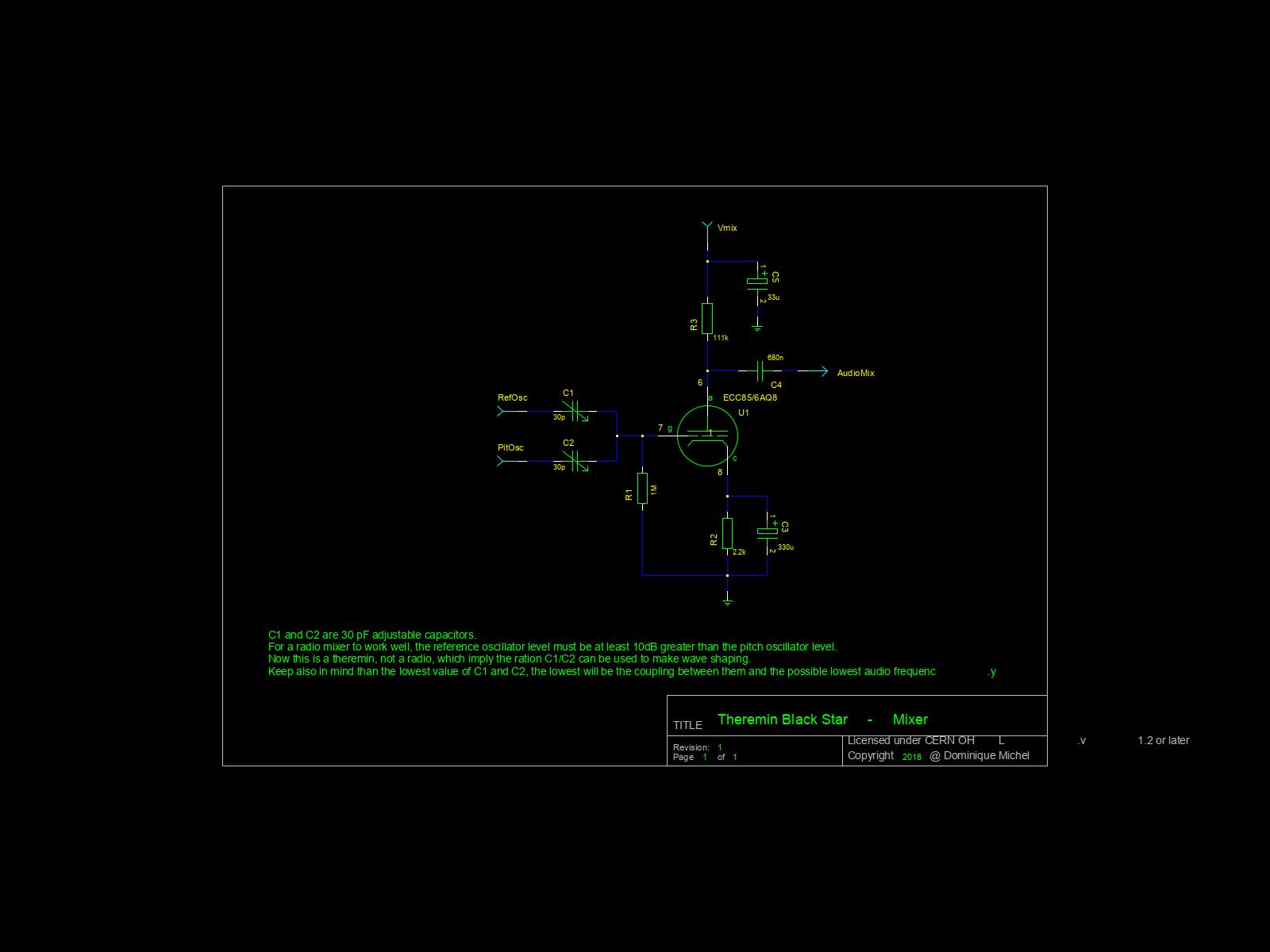
I just made some measurement. At 600 Hz, for 2V output at the HP and the VCA at full volume by stopping the volume oscillator, the mixer have a sensibility of 2.4 mV with the volume potentiometer at its minimum (It act more like a gain control) and without feedback on the output stage, and 5.4 mV with feedback. With the gain at its maximum, it give 1.2 and 2.6 mV.

The real sensibility is a little bit more, because the maximum output without visible distortion is around 3V, which give 1.8 mV at gain max and without feedback, which is almost the sensibility of most guitar amplifiers (around 1.2 mV). That volume potentiometer which act like a gain stage is very practical. It let me to chape the wave easily. In combination with the VCA, it is possible to get a distorted wave at all volumes, that without too much noises or hum. The output circuit is very well done because it give me 5.96 V RMS at full saturation, which imply it have a huge dynamic. Which give us 7.1 W EMs on a 5 ohms load (the impedance rating of the transformer, I didn't measured the speaker.) at full saturation and 1.8 W for a 3 volts output. The original speaker sounds good, as most speakers of that era, it is of the high efficiency type. The speaker of the fender champ sounds good too, with more basses and a little bit less trebles.

(As comparaison, a Peavey Mace with a push-pull of 6 x 6L6 is given for 160 W RMS without saturation... and 160 V RMs at full saturation. Half that saturation is made by the power transformer (I measured it, more than 100V of loos on the high tension coil at full volume), which result into a very bad sound at that level of saturation. They are good amplifiers to play jazz, but very bad to play heavy blues or punk. The saturation into the output transformers of a fender champ give a much better sound than the saturation of a main transformer. Don't be too rude with such amplifiers, or you will be in need to change their transformers sooner or later.)

Posted: 11/28/2018 10:46:49 AM
Dominique

From: Switzerland

Joined: 11/5/2018

For the waveform shape, it is 2 kinds of distortion a tube (or a transistor) can provide: input and output saturation. Input saturation is when Ug(peak) is greater than -Ugc, the grid become positive and act like a diode, and output saturation is when Ia become so low than the tube is in cutoff. With low power tubes, as Ig must be into the microampere range, it is enough to provide them with Ug(peak) > -Ugc for input saturation, and for clipping, -Ug(peak) must be great enough too. See http://www.valvewizard.co.uk/Common_Gain_Stage.pdf for a detailed explanation.

With power tubes,l it depend on the dynamic you want to archive. A 6L6 can take 2W on its grid (from the datasheet). These 2 W are in fact needed if you want a great dynamic with the lowest amount of distortion. Which imply, for a class B push-pull of 6L6, a driver made of preamplifier tubes will be totally inefficient at providing that power (2 x 2W = 4W) to the 6L6 grids, but an EL84 single ended stage with an output transformer will do that job. Another issue with such a driver is that the supply must be good enough to follow the need in current of the push-pull, that both for the anode and g2 supply. Also, the bias of the push-pull must be very conservative (I have warned you), that especially if you stabilise the g2 supply, which will give the ultimate possible dynamic.

You must be logged in to post a reply. Please log in or register for a new account.