Teensy 4.0 600MHz ARM Cortex M-7 MCU - ideal for digital MCU based theremin?

Posted: 11/5/2019 8:32:12 AM
Buggins

From: Porto, Portugal

Joined: 3/16/2017

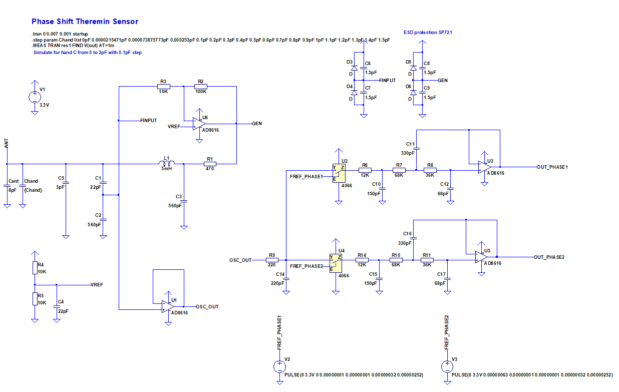
LTSpice simulation of quadrant heterodyne pitch sensor.

OpAmp based Colpitts oscillator with 5mH inductor (air core 32mm frame 0.1mm wire 70mm winding), tuned to produce ~10KHz frequency change between near and far hand distances.
Analog switch based heterodyne with quadrant output: requires two reference frequency signals - with frequency 1-4KHz bigger than minimal oscillator frequency, two PI/4 phase shifted switch enable pulses, with duty cycle = PI/4 or even less (depends on switch performance).
Output of two LP filters can be feed to Line In since it's in audio range for tuned theremin.

LtSpice model:


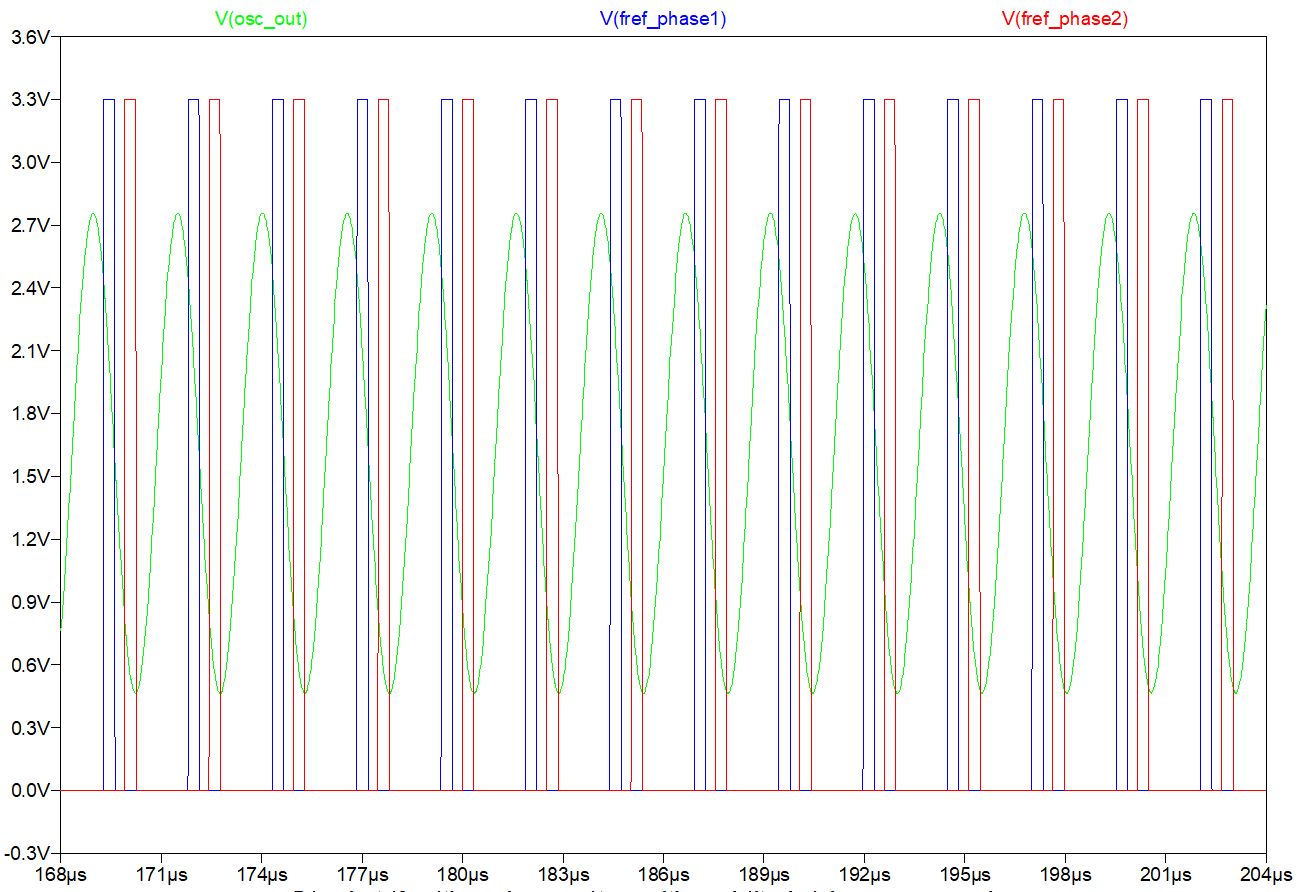
Simulation: oscillator output signal and two reference frequency pulses for switch enable:


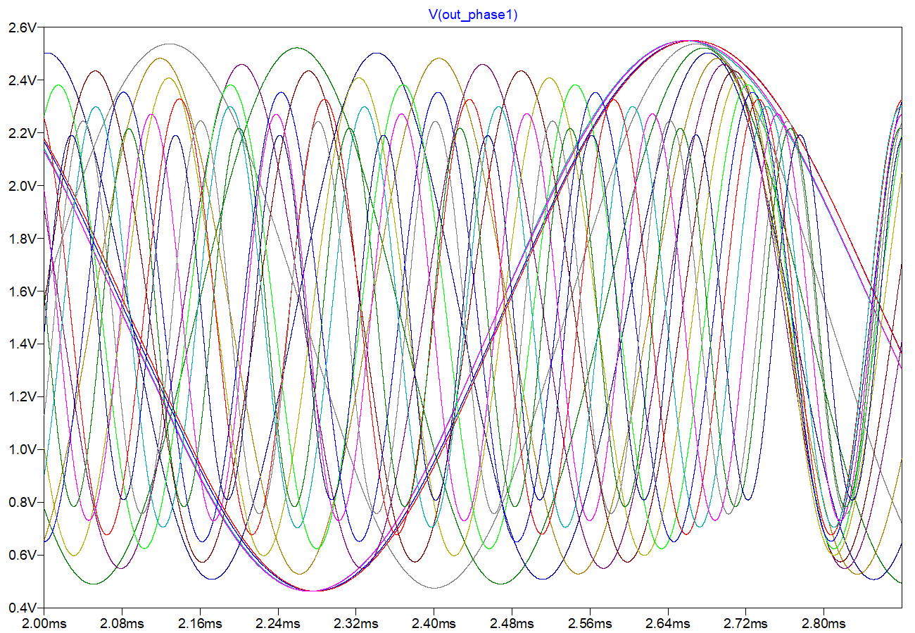
Single heterodyne ouput for different C_hand:


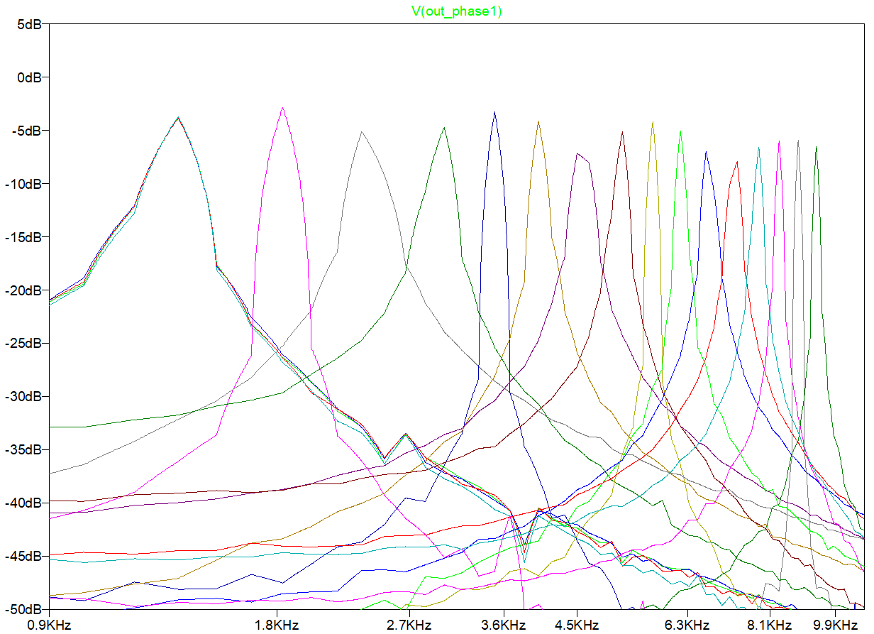
Heterodyne output FFT (peaks are not narrow enough due to short window length):


Two quadrants heterodyne output: 

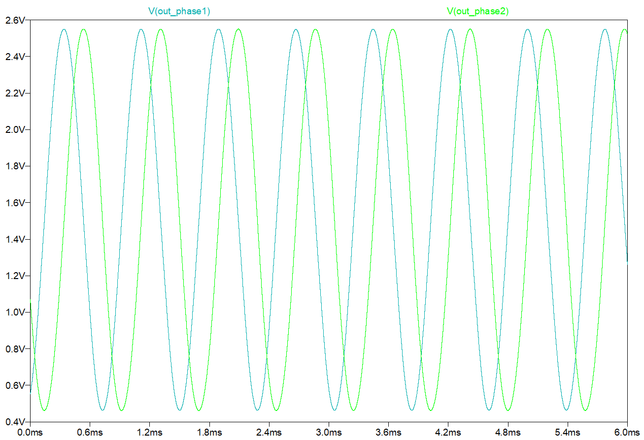
This signal may be sampled by MCU (e.g. using audio ADC) to calculate hand position from frequency.
Aplitude probably should be reduced to fit Line In range to avoid clipping (if ACD doesn't have pre-amp with K < 1).
Quadrant signals allow to eliminate amplitude changes - phase can be obtained using tan2() function.

Model to play with can be found on GitHubsin_osc_opamp_v1.asc

If reference frequency is less than 400KHz, Teensy 4.0 is able to generate it with <4KHz step precision (divider from 150MHz timer base frequency should be divisible by 4 to have exact quadrant values). So, output of heteridyne will vary 1KHz..11KHz to 5KHz..16KHz depending on oscillator frequency, if oscillator is designed to produce frequency change 10KHz for full hand distance range.
So, it's ok to use internal PWM or Timer for producing 2 phase aligned ref signals.

Posted: 11/5/2019 9:24:25 PM
dewster

From: Northern NJ, USA

Joined: 2/17/2012

Vadim, I'm probably just dense, but what is the purpose of quadrature here?  Does the phase difference between the two heterodyning outputs give you some information?

Posted: 11/6/2019 3:35:29 AM
Buggins

From: Porto, Portugal

Joined: 3/16/2017

Vadim, I'm probably just dense, but what is the purpose of quadrature here?  Does the phase difference between the two heterodyning outputs give you some information?

Phase difference between two outputs is PI/4 with high precision.

Having single sine output, it's hard to determine phase. Signal may vary by amplitude and phase simultaneously.Exact phase can be determined only at crossing of zero. If we track amplitude, other points may be obtained with asin() but sometimes it's hard to distinguish between sin(x+n) and sin(x-n) points.

Having two sine signals shifted by PI/4 is trivial: (a*sin(phi) and a*cos(phi)) gives exact phase using tan2() independently of amplitude of signal - for every sample. It even allows to track frequencies  f_sample < f < f_sample/2 - if phase diff between two samples is negative, use phase_diff = 2*PI-phase_diff
Both signals should have proper zero point calibration and relative amplitude calibration to produce precise results. But this approach is not sensitive to amplitude change of both signals together (e.g. due to damping while hand approaches antenna or due to increased tank C).

Posted: 11/6/2019 3:18:58 PM
dewster

From: Northern NJ, USA

Joined: 2/17/2012

Thanks for that explanation Vadim!

And thanks for the LTSpice file!  It made me install Wine (Win emulator) in Linux Mint so that I could run LTSpice, something I should have done on day one. 

When I open your sim file it complains that AD8616 and CD4066 aren't found.  I think it's OK to replace AD8616 with AD8618 (which is in the LTSpice library)?  What are you using for CD4066?

Posted: 11/6/2019 4:44:39 PM
Buggins

From: Porto, Portugal

Joined: 3/16/2017

Thanks for that explanation Vadim!And thanks for the LTSpice file!  It made me install Wine (Win emulator) in Linux Mint so that I could run LTSpice, something I should have done on day one.  When I open your sim file it complains that AD8616 and CD4066 aren't found.  I think it's OK to replace AD8616 with AD8618 (which is in the LTSpice library)?  What are you using for CD4066?

Hello,

I believe, I've downloaded collection of LTSpice components from http://ltwiki.org/?title=Components_Library_and_Circuits#A_Large_LTspice_Folder_from_Bordodynov

As an opamp I'm planning to use AD8052ARZ - fast low cost rail-to-rail opamp. AD8616 is used in simulation because there are only a few rail-to-rail opamps in library.

Instead of CD4066 I'm going to use ADG721BRMZ - fast two channel switch with small ON resistance.
CD4066 is the only analog switch I found in ltspice collection.

BTW, does your FPGA have dual channel ADC? If so, quadrant sine approach could provide better results than PLL based one.

Posted: 11/12/2019 1:03:24 PM
Buggins

From: Porto, Portugal

Joined: 3/16/2017

KiCad projects: opamp based oscillator with clean sine output.

Suitable for analog theremins as well.

PCB size is selected based on boxes I found for sensors (mounted near to antenna, contains long 11cm air core inductors on 32mm plastic tube frame).

Prototype PCB: GitHub link - for building on 2.54mm pitch prototyping PCB. ICs are actually soic-8 but soldered on soic-8 to dip8 adapter breakout.
OpAmp replacement: any 3.3V rail-to-rail pin compatible.
SP721 - no replacement, but optional if you don't bother about ESD protection.

SMD version of PCB: GitHub link


Use this LTSpice model for simulation.

Posted: 11/13/2019 11:20:43 AM
Buggins

From: Porto, Portugal

Joined: 3/16/2017

Created Teensy 4.0 Digital Theremin thread on Teensy (PJRC) forum.


Posted: 11/15/2019 4:59:18 AM
Buggins

From: Porto, Portugal

Joined: 3/16/2017

Trying to play with simplified phase shift based sensor - less analog.

Let's pass reference 50% duty cycle signal generated by MCU to LC, get shifted value back to MCU.
Instead of using XOR to make PWM, just measure shift between original signal and output of sensor.
Eliminated stages: XOR phase shift to PWM, PWM to voltage LP filter, ADC to get digital value of PWM duty cycle.

Is it possible to measure phase shift effectively on Teensy 4.0?
Answer is yes.

imxrt1060 user manual link

Time / pwm resolution is F_BUS = F_CPU / 4
For default 600MHz cpu clock, it's 150MHz; overclocked 800Mz (working even w/o heatsink) - 200MHz, overclocked 1GHz - 250MHz (heatsink required).

FlexPWM hardware block module allows to do following:
Generate PWM (set full interval, positions for switching to 1 and to 0)
Setup capture by external pin of PWM counter - it can capture both position of raising edge and position of falling edge of shifted signal (relative to reference signal phase).
I would be possible to read captured values via interrupt, but signal frequency is a bit high for interrupts - 500-1000KHz.
Instead, we can use DMA channel to get captured data and put into ring buffer w/o CPU.

Posted: 11/15/2019 2:02:56 PM
Buggins

From: Porto, Portugal

Joined: 3/16/2017

For 650KHz signal, we have about 8 bits for full PWM period:
Normal mode: 600MHz CPU, 150MHz BUS, 150000 / 650 = 230 timer cycles
Overclocked: 800MHz CPU, 200MHz BUS, 200000 / 650 = 307 tymer cycles
By measuring interval for both edges, we can double resolution: +1 bit = 9 bits
Averaging for 1ms: 650KHz / 1000Hz = 650 = ~9 bits
Assuming that doubling of number of averaged samples gives 1 bit of precision.
Total bits collected after averaging: 18

C_hand reduces ~3.5 times each 10cm
Distance, cm    C_hand, pF
1               1.5000000000
11             0.4285714286
21             0.1224489796
31             0.0349854227
41             0.0099958351
51             0.0028559529
61             0.0008159865
71             0.0002331390
81             0.0000666111

0.1pF step near resonance produces shift about 1/12..1/16 of full period - less by 4 bits than total range: 18 - 4 = 14

All distances starting 21cm fall into 0.1pF range, so 14 bits left for distances > 21cm
Each additional 10cm eats 1.8 bits of sensitivity (/3.5).
Starting 31cm 12.2 bits left
Starting 41cm 10.4 bits left
Starting 51cm 8.6 bits left
Starting 61cm 6.8 bits left
Starting 71cm 5 bits left
Starting 81cm 3.2 bits left

Usable hand distance range, according to these calculations ends at 60-70cm, if it's not possible to use more averaging.

Adding x4 averaging (4 ms latency instead of 1ms latency) adds 10cm of playable distance.

LTSpice model github link

Inductor is air core, 32mm plastic frame, 90mm winding of 0.1mm copper wire.
F_ref is near 650KHz.

Instead of direct digital square signal, LC input is fed by sine made by bandpass LCR filter tuned to 650KHz - to minimize distortion.
In this version, 0.1pF C_hand causes only 2.3% of phase shift, although I saw 8 and 12% when played with model.
Will try to increase sensitivity.

Posted: 11/15/2019 11:01:21 PM
dewster

From: Northern NJ, USA

Joined: 2/17/2012

Vadim, I haven't checked your numbers, but I believe you are absolutely on the right path with your calculations.  I'm not saying you are right because it is what I did too, just that it's very interesting to see someone else working the numbers before committing to hardware. 

I directly see a lot of resolution reduction in the far field on my D-Lev, particularly since I reduced the influence of AC hum, and made the bandwidth track hand position (less BW with the pitch hand farther away).  This is masked a lot by the far field pitch being naturally low so the human ear can't hear pitch very well, and the dithering of AC hum can actually help resolution to some degree.  Anyway, what I see is much in line with your numbers.  Playing out around 1m is probably not a realistic goal anyway, as the rest of the body and other disturbances in the area will dominate.  I find playing in the far field is somehow less comfortable than in the mid and near fields, even though the linearity can be made quite good throughout.

It seems you're searching for a way to do a pro-grade Theremin with the bare minimum of hardware?  I'm not saying you shouldn't attempt this (it can be a fun puzzle to sove), but a small FPGA or other dedicated logic isn't too expensive for people to purchase in their pro Theremin?  The case and other stuff will likely swamp the cost of the guts.  To me, making the thing easy to own (simple to tune and adjust) is job #1.  Making it playable is job #2.  Making it sound good is job #3.

I applaud your tenacity!

You must be logged in to post a reply. Please log in or register for a new account.