"I just want to have the ability to detect such condition. For volume antenna, touch or double touch can toggle mute. For pitch, it should continue to use highest (last detectedd) pitch. Stopping of oscillation can be detected as touch as well. But I'm not sure if recovering of oscillation at end of touch will not cause any side effects." - Buggins
If you have a volume axis polarity option that lets the user pick closer=louder, then muting via antenna touch would require them to play a loud note in order to mute, which would be weird. Accidental touch of volume could mute during performance. And encouraging the user to stop the oscillator is kind of asking for it IMO. There are plenty of ways to positively mute / unmute, and I'd pick one with the fewest opportunities to wreak havoc, preferably something mechanically positive, and not a touch switch or anything that brushing against could easily toggle.
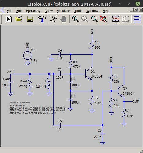
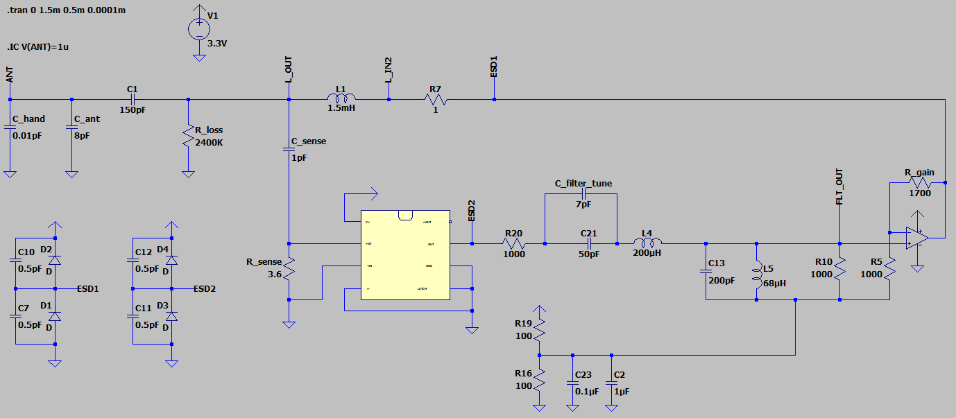
"Will try to reduce C between LC tank and amplifier a bit more."
"Can believe MOS should give smaller input current and allow smaller C (I think 1pF is good goal)."
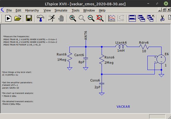
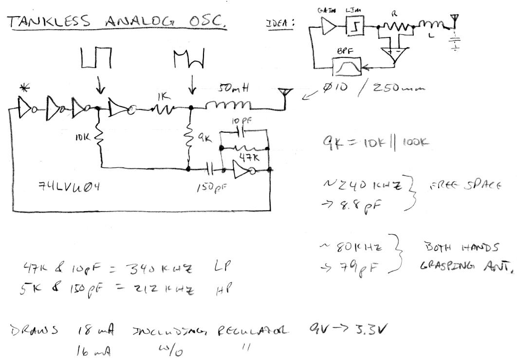
The problem with these types of oscillators is that the coupling capacitor works both ways, so reducing it to increase absolute sensitivity gives a double whammy by reducing both sense and drive, wussiness squared.
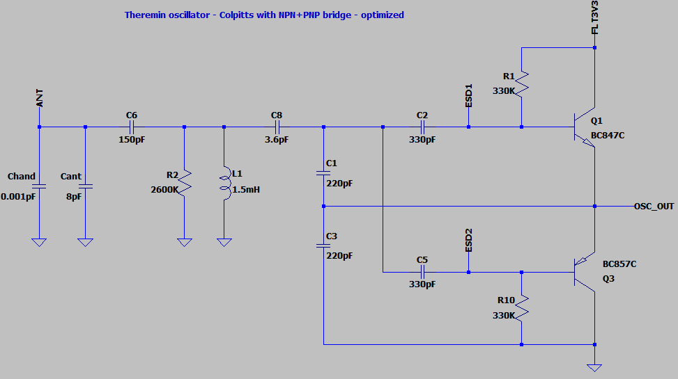
"Solution is to use the same PCB and even the same NPN+PNP transistor. Some wires should be cut and some components not soldered to exclude PNP part.
This will guarantee fair play - same transistor and same regulators will be used for comparision."
I was thinking the same thing!
"I believe a big portion of noise comes from digital signal edges.
It applies even to your phase detection approach.
If averaging still gives enough bits, does it make sense to reduce frequency of oscillator by increasing of L?
Twice less edges - twice less noise from edges."
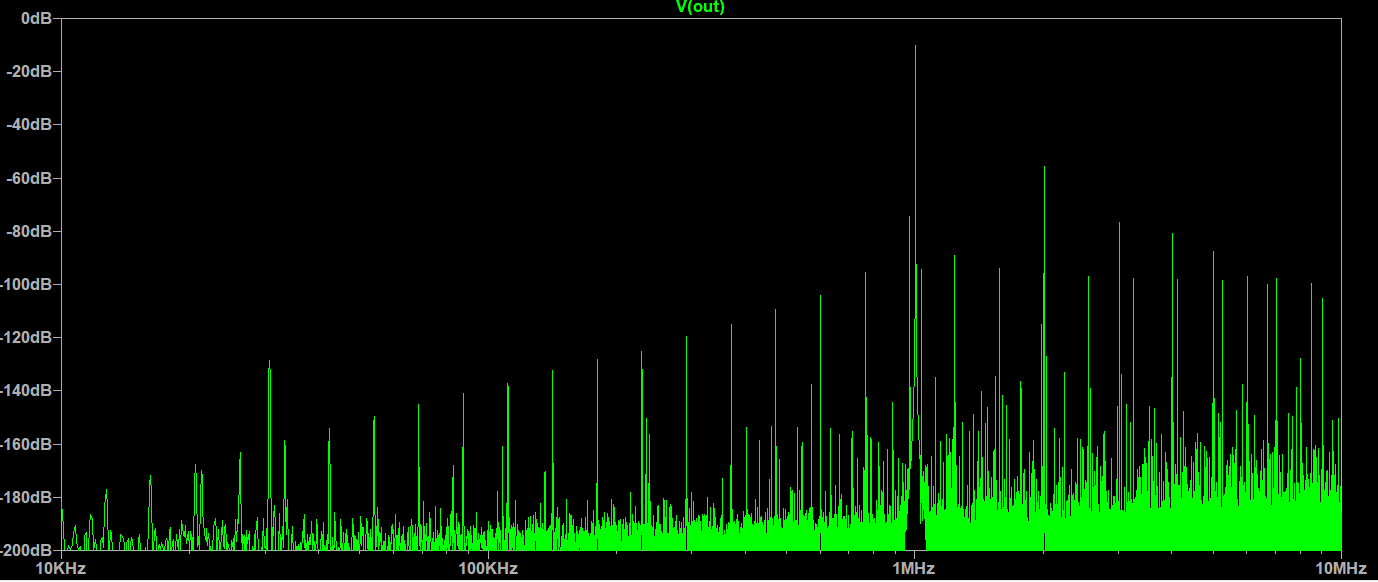
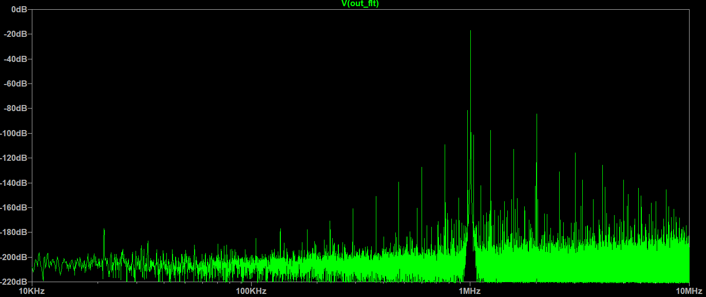
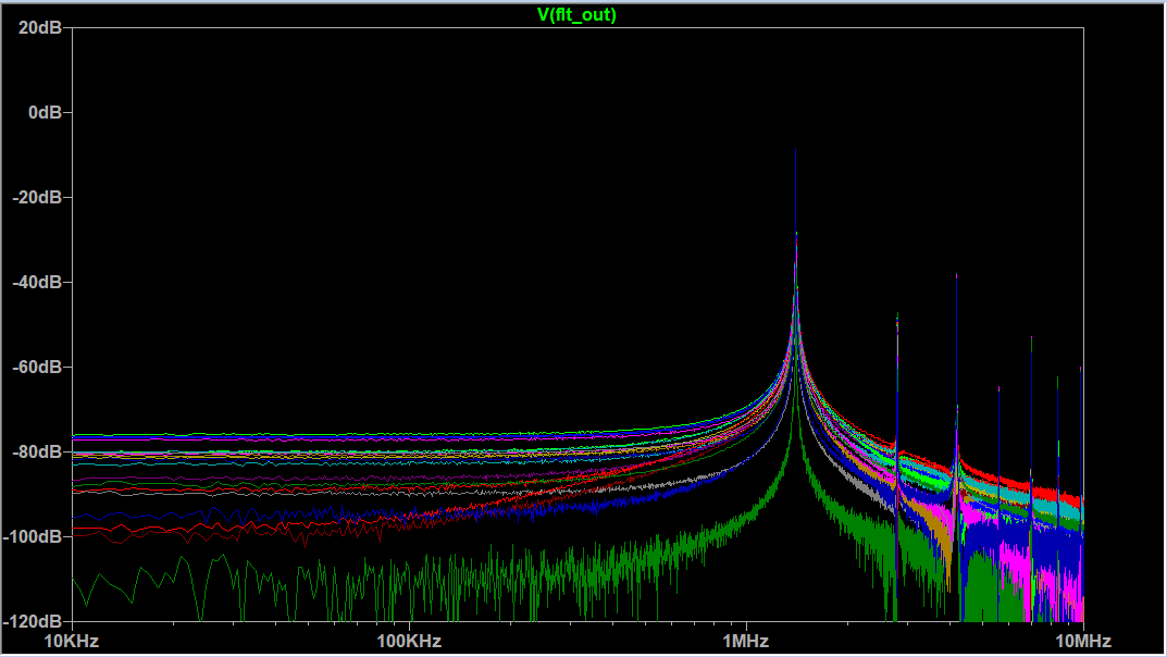
True, each measurement introduces noise, so noise goes up directly with measurements, but averages down by the square root of measurements (if we are limited to simple averaging). But you can't filter out aliasing, which is anything above 1/2 the sample rate (LC oscillation frequency). Most noise is mains hum, but it's something to think about.
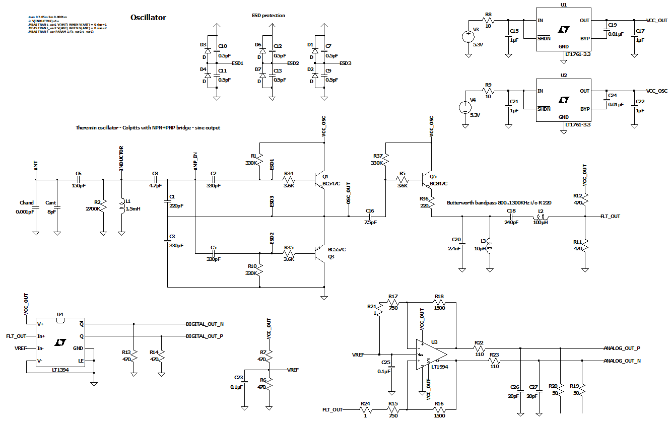
"If we could produce clean sine wave signals from oscillator, 2 or 4 shifted by PI/2, then put it to fast ADC (single ended for 2 signals, or differential for 4 signals), precise frequency measure of oscillator becomes possible.
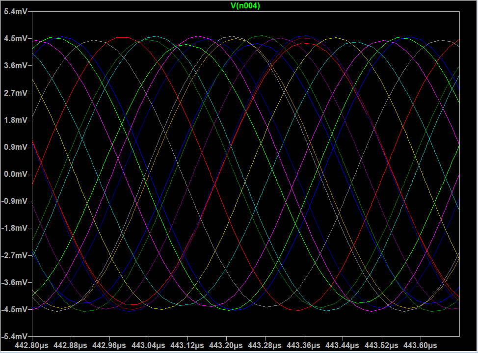
For PI/2 shifted pair, atan2(sample1, sample2) can be used for getting phase value. Averaging of phase measures sequence may filter out a lot of noise and provide enough number of bits.
4 wire 2 differencial pairs should reduce noise from oscillator to ADC line.
This approach is possible for FPGA with fast ADC (e.g. 100MSPS)."
I agree, and then you would be truly sampling without squaring things up (a non-linear process), which would take anti-aliasing up to 50MSPS in your example, rather than LC freq/2. And driving the tank with a sine wave would eliminate injected harmonics and the need for dither. That would be a perfect world.
My DPLL approach at least drives with a small square wave into high Q LC with no phase error, which gives a really nice big ~pure sine wave at the antenna. And the sensing edges are 90 degrees from the driving edges, which gives things time to settle. The squaring has analog DC balance (inverter R feedback), but the DPLL itself can work with somewhat imperfect duty cycles. You have to pick your battles with this stuff and do the best you can with what you have (the whole reason for your project :-). The general environment and emissions from your own circuitry can work against you at every step, and stuff inevitably happens when measuring femto-Farads in real-time.


