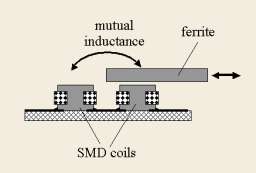
I found a general concept I like and try to build it verbatim, but feel forced to tinkering in order to be able to source parts. In the "Paradox" design the oscillators topology has nothing to do with the sound, they could very well be producing square waves. The mixing is, so to speak, already accounted for, by ILYAs eminent design. The only way the waveform is important there, is in the interaction with the antenna. Waveform generation is disconnected from sound mixin[/font][/size][/color][color=#333333][size=2][font="Helvetica Neue", Helvetica, Arial, sans-serif]g by a digital counting stage (again, save for jitter and side channel noise, e.g. loading of power rails).
I like Paradox design - "registers" idea, linearization via divider, xtal fixed oscillator, original VCA.
The only thing which is bad here is primitive mixer.
If there is no goal to make design as simple as possible, we could try to replace mixer with more advanced one.
I've played a bit with LTSpice... You can see results below (WARNING: a lot of pictures)
There will be a lot of pots for tuning of each register and mixing them together.
1) Instead of buttons, when mixing registers, use POTs - for proportional mixing of register components.
2) Use better mixer - separate mixer/heterodyne per register - based on analog switch and lowpass filter.

For such mixer, square waveform of reference and variable frequencies is not a problem.
If two squares are passed to enable and input pins of analog switch, output of LP filter will be clean triangle with exact F=F_ref-F_osc. It already sounds better than square.
It's just a starting point for experiments.
Initial LTSpice model to play with on GitHub
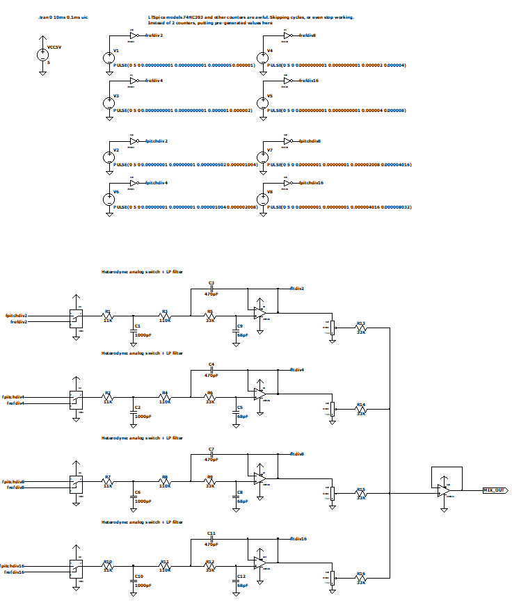
Counter models in LTSpice are don't work for me, so I replaced counter outputs by square pulses of proper frequencies (1MHz for /2, 500KHz for /4 etc).
Output of 4 registers and combined value:
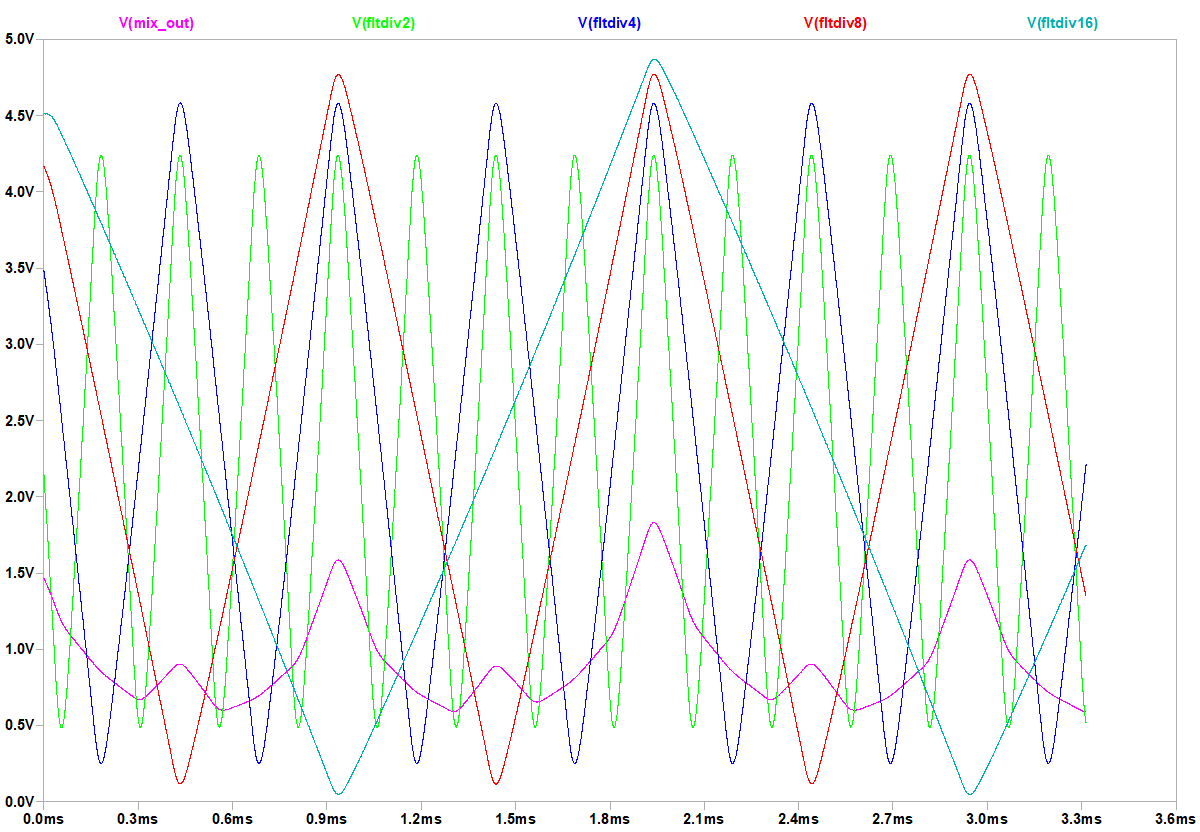
There is almost no difference between reference freq on enable with variable osc on input of analog switch and opposite assignment.
Ref frequency is const, but variable pitch oscillator is nearly const, too, changing for ~3-5% only.
Why this mixer produces triangle for two squares on inputs?
Actually, it's a kind of "moving average" filter for signal on switch input, for time while enable pin of switch is active.
If enable pin duty cycle = 50%, moving average filtered square is triangle.
We can reduce duty cycle, making enable impulses shorter and shorter. For shorter enable pulses, shape of heterodyne output is getting closer and closer to shape on switch input.
If we add pot to change pulse width from very short (~1%) to wide (50%), we can control averaging filter. For square on input, output shape will morph between square and triangle.
As well, it make sense to add pot for changing of enable pulse phase. Phase shift of input signal is applied 1:1 to output signal. It would allow us to mix registers with different phase shift (I believe, relative phases are audible important when mixing several registers).
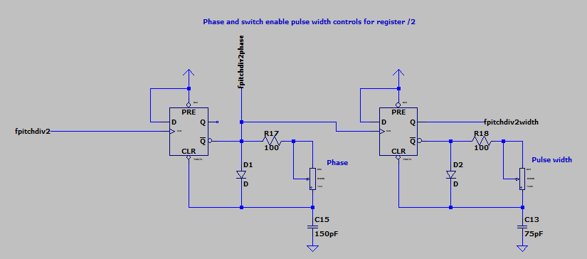
It's similar to 555 timer monostable schematic, just on D triggers instead of 555. (555 did not work for me, I've tried).
First pot shifts positive edge of signal by up to 0.95 of period.
Second pot changes pulse width between 0.01 and 0.5 of period.
RC should be tuned separately for each register.
Then, we can shape input signal as well.
Since it's either fixed frequency or changes only by 3..5%, we can apply a lot of signal shaping techniques which are not available for audio signal frequency ranges. E.g. we can use RLC bandpass filter to get clean sine wave from square.
Let's add pot to morph input signal between sine and almost square (and even some strange waveform, I don't know how to name it).
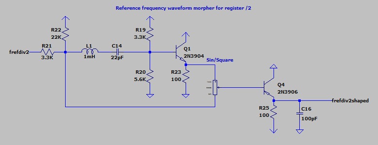
With short pulse width this shape will be converted to register audio signal as is. With increasing of pulse width, upper frequencies are getting filtered out.
E.g. sine becomes really pure after this filter.
Two signals mixed with pot to create different shapes. In middle position it's close to square wave. Below you can see sine, strange shape, and mix of them.
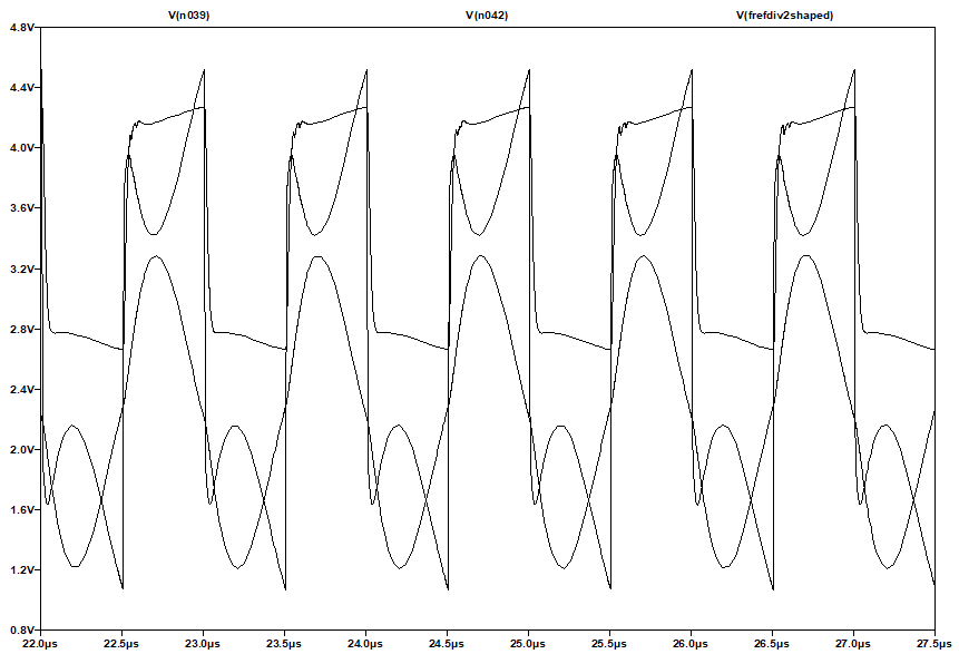
Mixer inputs. Analog switch "enable" pulse "samples" waveform of switch input signal.
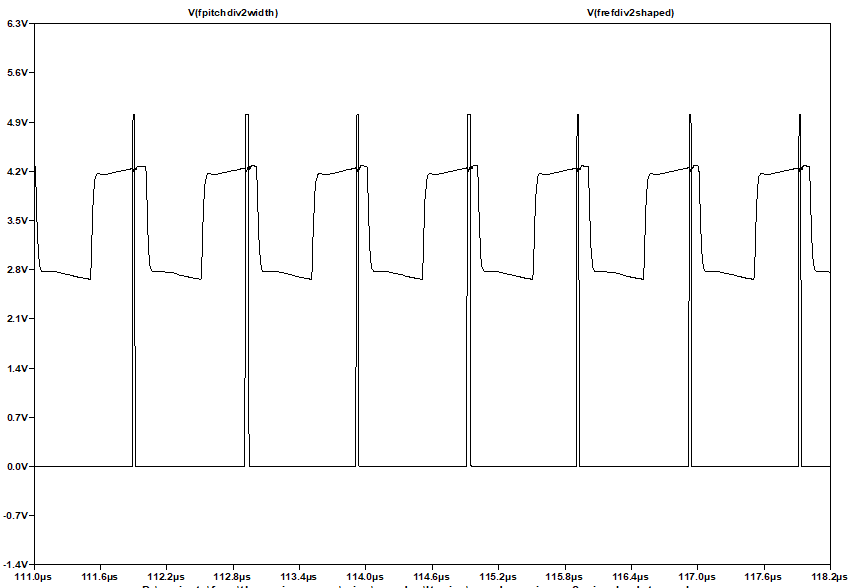
Mixer output for these inputs: shape is almost the same as input waveform, because sampling pulse is short.
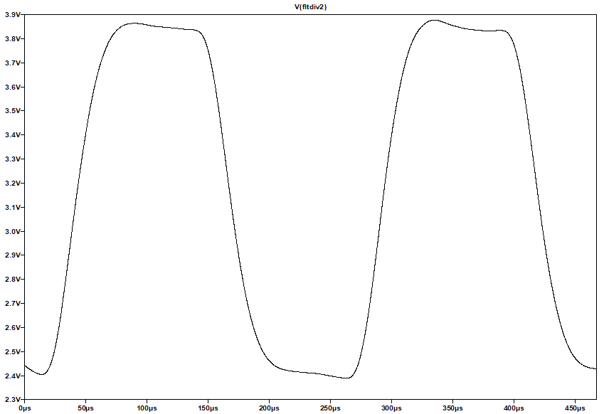
When shape pot is close to 0 position, and pulse width close to widest, output of heterodyne is very clean sine:
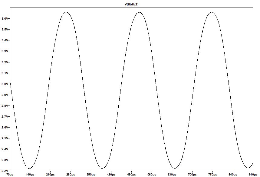
It's just a sample shape control. Any other may be used.
LTSpice model with 3 additional pots per register.
Only /2 register has pulse phase/width and signal shape pot controls in this model.
You can add them for the rest 3 registers.
They should be tuned to lower frequencies: phase/width - increase capacitors *2, *4, *8 times.
For signal shape control, use RLC calculator (probably, you would just need to use *4, *16, *64 multiplier for caps).
In proposed design, there are 4 pots per register:
* phase shift (for relative moving of register signals)
* pulse width (moving average filter control)
* shape (sine .. square .. near sawtooth probably)
* volume of register (for mixing in different proportions - replacement for pushbuttons of original paradox).
In total, there are 16 pots in this mixer 
But I believe there is a really wide range of possible shapes is possible to achieve with different pot positions.
Sine / triangle / square / and much more waveforms, mixed from several registers with different phase and amplitude.
UPD: spice models for used components are available on GitHub
![]() I have an old design of a 24 bit software DDS in an MCU, but it cannot reach the frequency needed. I think I can hear you all facepalming from over here!
I have an old design of a 24 bit software DDS in an MCU, but it cannot reach the frequency needed. I think I can hear you all facepalming from over here! ![]() ).
).


