"Have you really tried buffered inverters? I didn't expect that they would work ![]() " - Buggins
" - Buggins
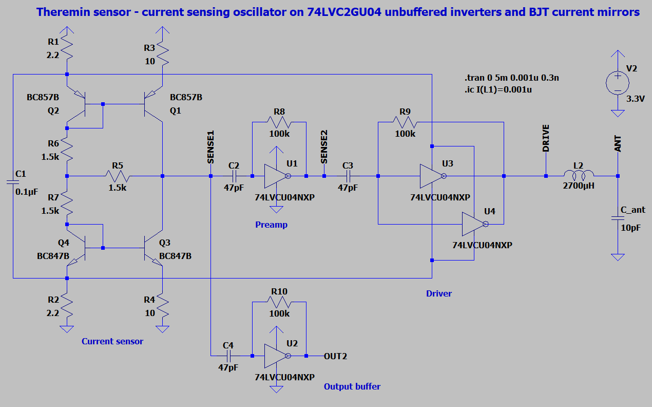
Yes, except for the LVU I think the other two are buffered.
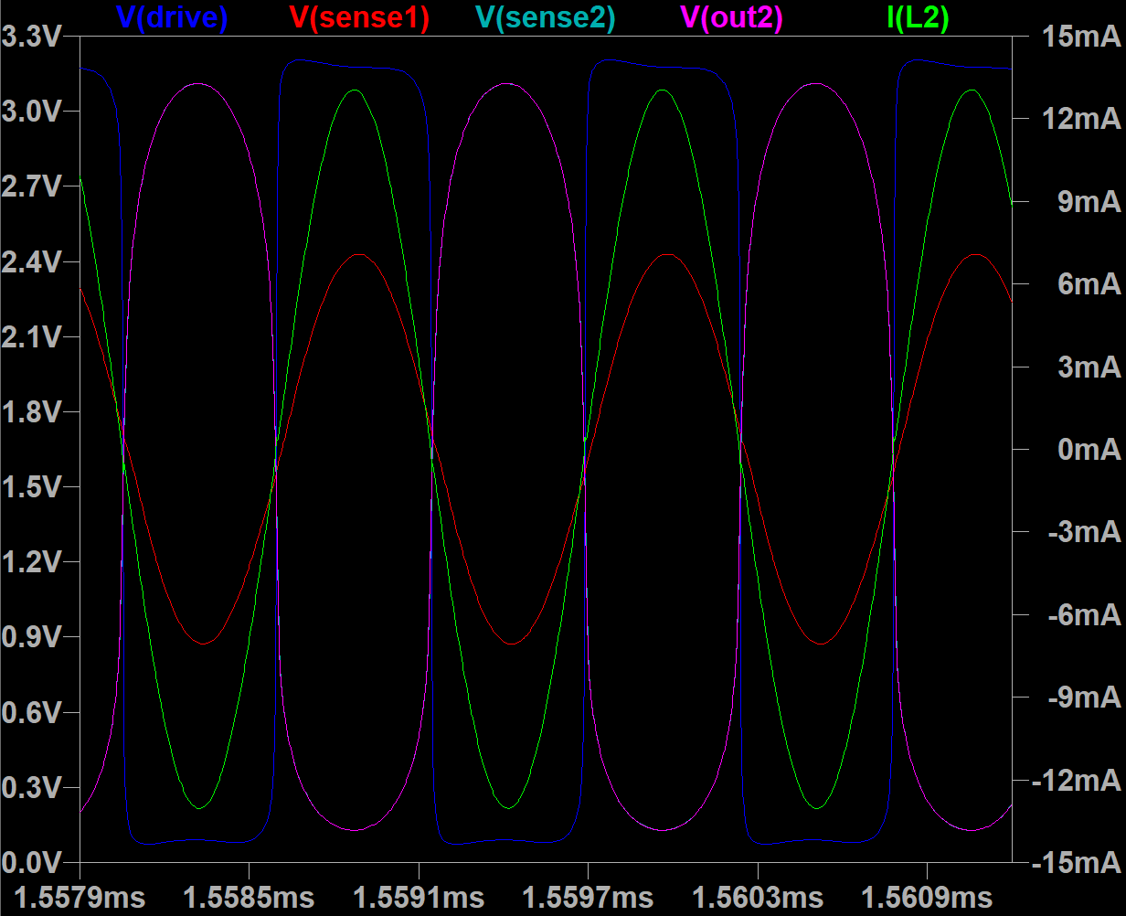
"For LVU, you can try changing sensing inverter input cap value - it allows changing of phase. Probably, it's possible to achieve zero phase error by using of proper decoupling capacitor and feedback resistor. I believe, input cap should be tuned for different LC tank frequency."
I should give that a try, but the unbuffered phase delay seemed significant. I haven't played with your simulation at all either.
"Does inverter bases current sensor oscillator survive hand touching antenna?"
At first I was only using one 74HC04 inverter for the coil drive. It would stall sometimes at power-up, and it would also stall if I touched the antenna. The only way I could get it to start after that was to touch the drive end of the coil - weird. Once I wired up all 5 inverters for the drive it would only stall when I pinched the antenna, and it would start right back up after I let it go. I think using 22 ohm resistors instead of 10 made it a little harder to stall (that experiment is necessarily rather inexact).
"I believe only buffered inverters have hysteresis."
I think that's true.
"But oscillators are analog devices, and I believe it's better to use unbuffered inverters there."
I agree, but you then have to find ones that are fast enough. I think most applications want speed rather than linear biasing / amplification, so these components are becoming rather rare.
"Eric, do you think it's ok to implement output this way? If so, only two 74LVC2GU04 ICs are needed."
It certainly looks good in simulation, and the circuit is beautiful, but the true test is trying it out, and unfortunately I don't have any LVCU devices on hand.
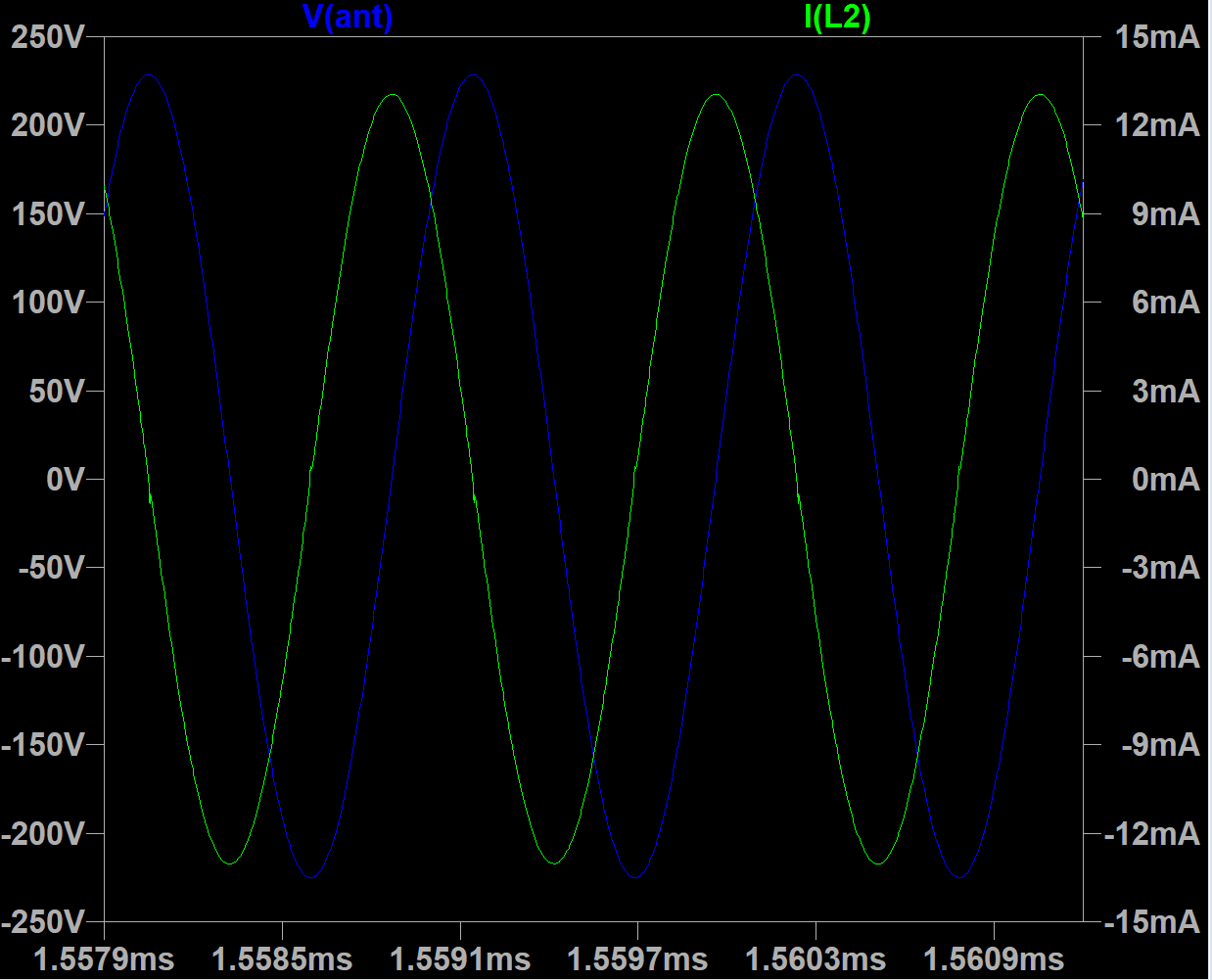
"Oscillator draws ~80mA in this configuration."
I would start to worry about oscillator frequency heating drift with current that high. It's too bad the oscillator couldn't somehow store the the drive current from one side of the swing and use it for the other, rather than pulling it from VCC / ground.
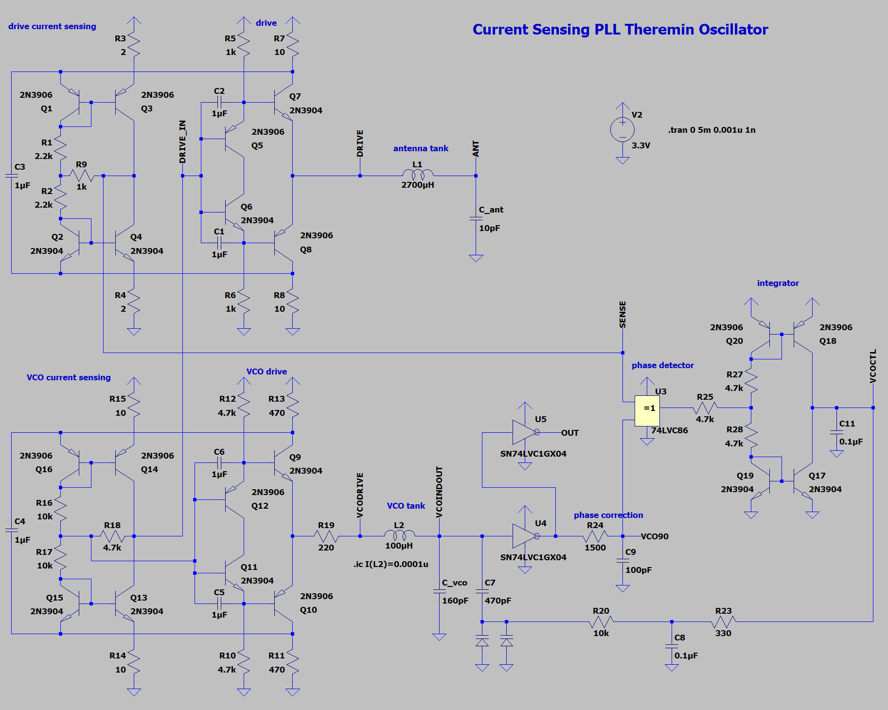
My next move is to breadboard the 10 transistor active load oscillator to see if it works as well or better than the 8 transistor. Even though the drive resistor is in series, I think / hope these perhaps offer the best way forward. The packages may shrink to the size of a flea, but we'll be able to purchase individual transistors for the foreseeable future, and it's probably better to have BJT's rather than CMOS connected to an antennas for ESD reasons. You're sort of experiencing what I went through looking for logic to "do the right thing" in an analog situation. I found LVU but then they discontinued it in DIP packaging, so I was forced to switch to AHC, which seems to have much better centered Vt.
I'm not trying to dampen your enthusiasm, but DPLL's still seem to me like the best solution here. Because phase error is differential and decoupled from frequency, they are essentially feed-forward, so there are no real logic speed issues. And digital oscillators / phase detectors / phase accumulators have no intrinsic noise to contribute. And all kinds of environmental noise can be quashed by lowering the loop bandwidth to 100Hz or so. Someone should make an inexpensive FPGA of some sort that we could use at each antenna. Do heavy filtering inside it and transfer the operating point back to a processor serially at a 48kHz sample rate. If the DPLL had a bit of D/A at the output, triangle (rather than square) wave stimulation of the coil could get around a lot of the dither and pin switching speed issues. True analog mixing / phase detection, or a bit of A/D at the input could get around most aliasing issues.
That said, DPLL's can be difficult to get right, and voltage variations at the various pins can cause trouble. And I'm convinced that you can make a pro-level Theremin using stable, relatively high voltage analog oscillators.


