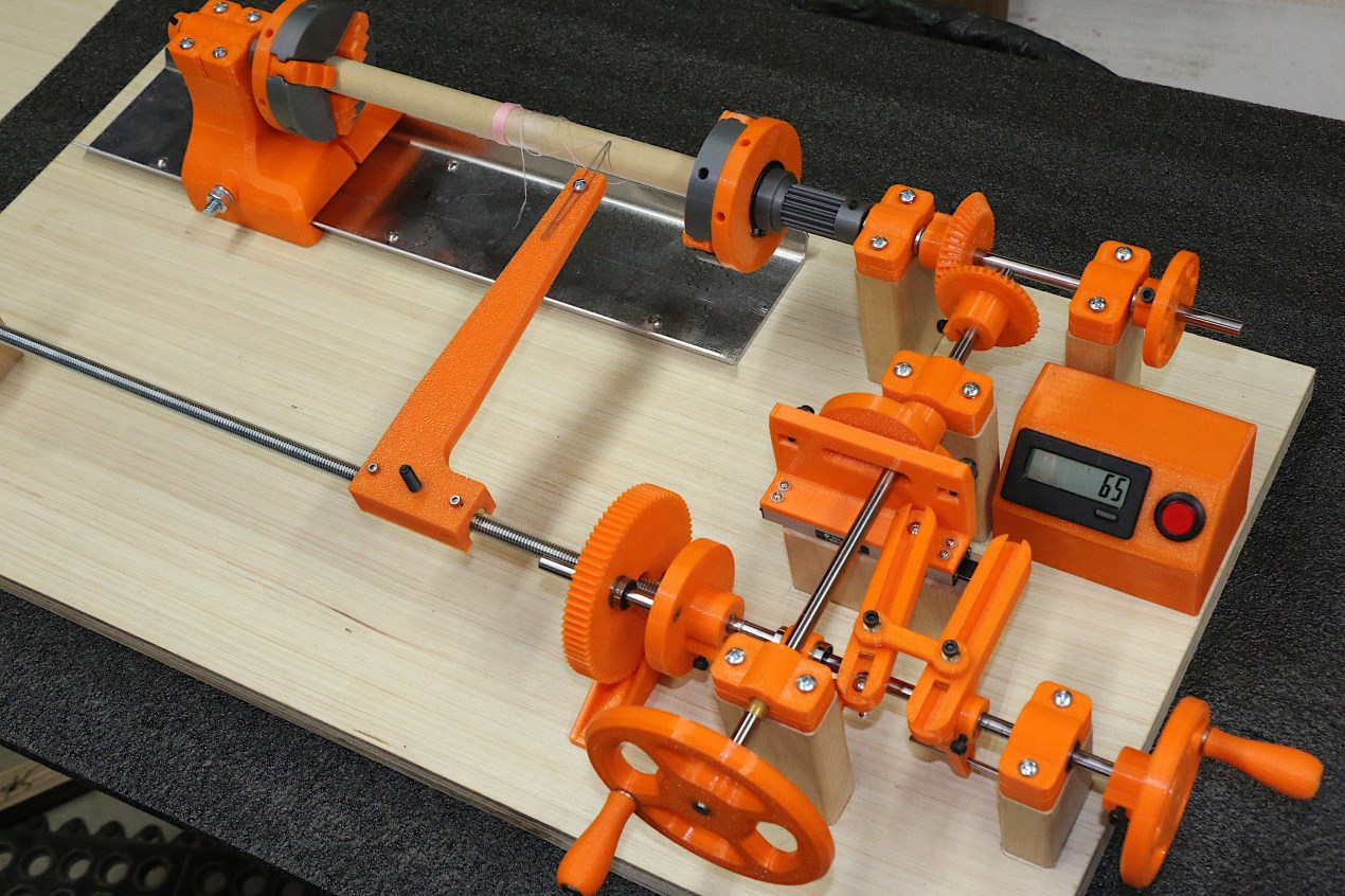
This (mostly) 3D-printed coil winder is still a work in progress, and it will be some time before I get the progressive portion of the winder working.
As part of my Moog Melodia replica project that I started a long time ago but haven't finished, I needed to make some sort of "universal" or honeycomb winder for the four tunable inductors and transformers. Adding to the complexity was the fact that the antenna inductors are wound on ferrite cores using what is known as a "progressive-universal" machine winding process. As near as I can tell this combines the layered helical winding action of a standard honeycomb wind with a slow transverse motion of the wire feeder in an effort to spread the winding over the length of a core. That is all I know about it at this point, and I am expecting to figure out more as I play with various transverse feed rates as a ratio of the rotary motion.
The basic universal portion of the winder works like an old fishing reel. As the core is rotated the wire is fed with a linearly reciprocating action so that adjacent windings are spaced apart from one another and the criss-cross patterns of subsequent wire layers avoid windings running parallel to each other. The whole point of this is to minimize inter-winding, inter-layer, and end-to-end capacitance of RF inductors, a parasitic that lowers the self-resonant frequency (SRF) of the coil. The progressive part of the winder I presume helps to spread out the length of the coils to reduce capacitance from one end to the other.
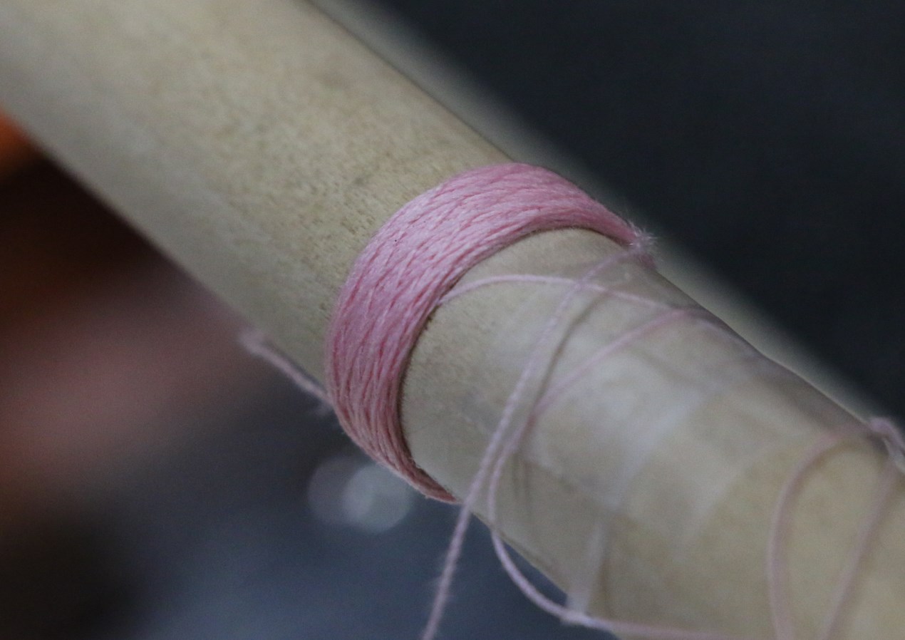
I will talk about this more later, but for now I simply have a teaser picture of the coil winder under construction. Files for the 3D-printed 3-jaw chucks came from thingiverse.com, but everything else is my own design done in Fusion360. I won't know if it works until it's done, because I have found almost no information on the intertubes. All is subject to change. But the second picture shows that the universal/honeycomb portion is working, at least if your goal is to print inductors made from pink thread.
[edit]
Description:
1) Foreground crank is for winding; the right crank turns the lead screw for fine-tuning the start position.
2) The bevel gear on the end of the crank shaft is fixed at 39 teeth.
3) The bevel gear on the chuck shaft is changeable with 38, 40, 42. and 44 tooth (shown) options.
4) The bevel gear ratio sets the winding angle of the helix. The 39 tooth odd gear ensures that subsequent wind layers do not stack directly on one another.
5) The linear cam on the crank shaft was designed to maintain a constant chord length through the diameter at any angle. This allows the use of push-push ball bearing followers so that a return spring is unnecessary. The stroke is 1 inch.
6) The two arms with the dumbbell-shaped link between them allows infinite adjustment (by moving the link position) of the reciprocating stroke from zero to one inch.
7) The lead screw moves laterally on linear ball bearings. All wear points are either ball or brass sleeve bearings.
8) The large gear in the foreground and the spur gear at the hub of the drive chuck are part of the yet-to-be-completed progressive drive train. As the chuck rotates this motion will be transmitted through a gear train (not yet designed) to the large gear, causing the lead screw to rotate and in turn causing the feed arm to translate left or right. There are two linear bearings in the gear that allow the lead screw to rotate while freely moving laterally.
9) The feed arm shown is temporary. The final one will have wire guides, and roller above the piano-wire feeder, and a friction tensioning knob at the base.
10) The aluminum tray was originally intended to be a protective pan for when shellac or other bonding liquid is applied to the coils. I decided to make it the dovetailed tailstock guide rail as well.
11) In the incomplete state shown the winder operates in universal mode only. As the crank handle is turned the cam pushes the follower plate left and right. A ratio of this linear stroke is transmitted to the lead screw so that it moves laterally with every rotation of the crank. The feed arm contains two brass half-nuts that rest on the threaded rod, held in place by magnets. This allows the arm to be picked up and moved to the desired spot without having to turn the small crank a bunch of times.
12) There is a magnet embedded in the wheel above the counter module to trigger a sensor, but I'm going to replace this all with a cam an a small mechanical counter. The counter shown takes up too much space that I want to leave available for the possible addition of a variable speed motor.
13) The wire spool will be supported on a roller tube at the lower back of the base. The wire will feed slightly above the base and over the metal tray to the base of the feed arm. This will keep the wire out of the way of the action.
I'll post more pictures and a video when it's done.


