Build Project: Universal/Progressive RF Coil Winder for Theremins

Posted: 11/12/2020 11:45:06 AM
pitts8rh

From: Minnesota USA

Joined: 11/27/2015

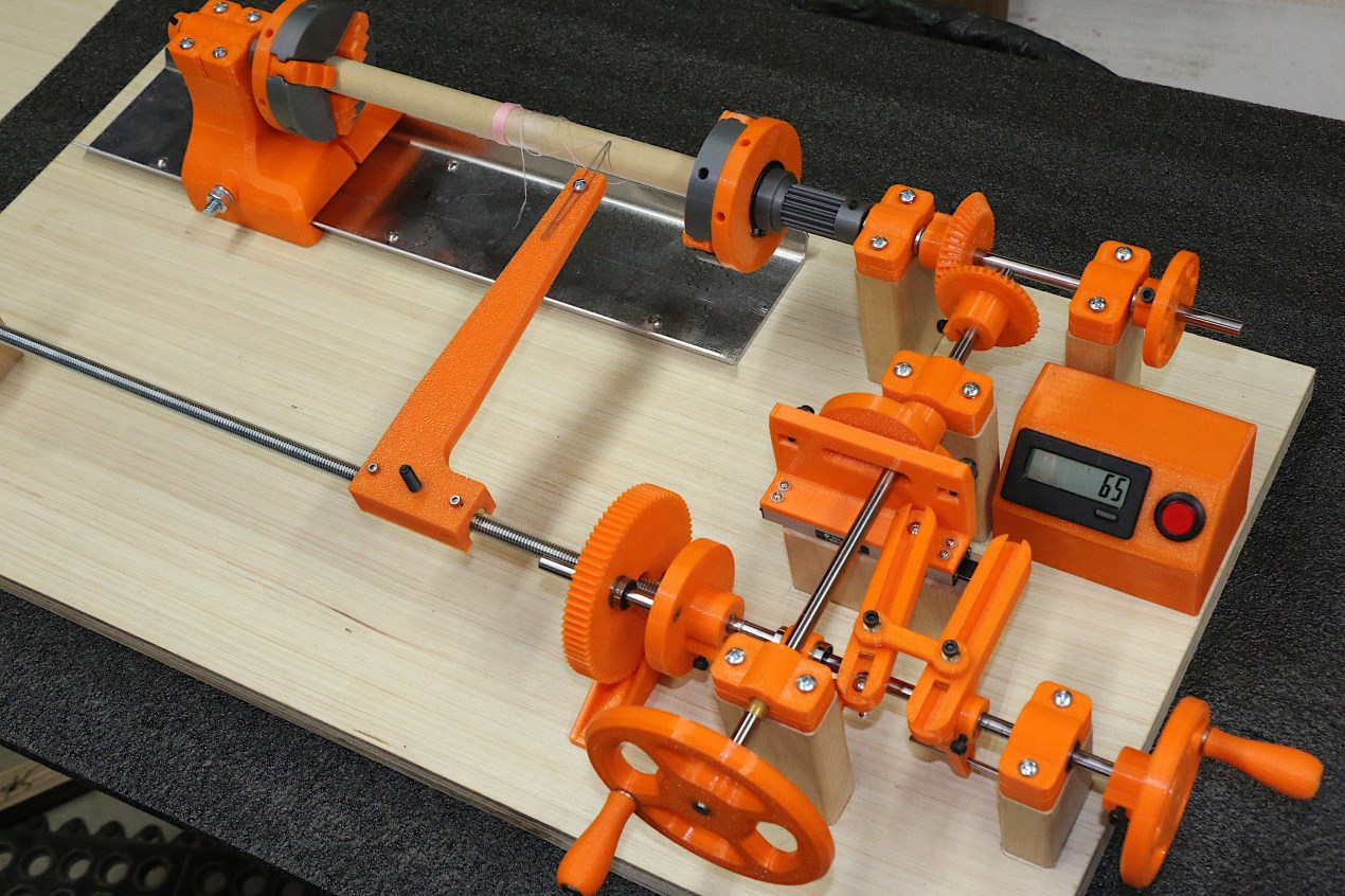
This (mostly) 3D-printed coil winder is still a work in progress, and it will be some time before I get the progressive portion of the winder working.

As part of my Moog Melodia replica project that I started a long time ago but haven't finished, I needed to make some sort of "universal" or honeycomb winder for the four tunable inductors and transformers.  Adding to the complexity was the fact that the antenna inductors are wound on ferrite cores using what is known as a "progressive-universal" machine winding process.  As near as I can tell this combines the layered helical winding action of a standard honeycomb wind with a slow transverse motion of the wire feeder in an effort to spread the winding over the length of a core.  That is all I know about it at this point, and I am expecting to figure out more as I play with various transverse feed rates as a ratio of the rotary motion.

The basic universal portion of the winder works like an old fishing reel.  As the core is rotated the wire is fed with a linearly reciprocating action so that adjacent windings are spaced apart from one another and the criss-cross patterns of subsequent wire layers avoid windings running parallel to each other. The whole point of this is to minimize inter-winding, inter-layer, and end-to-end capacitance of RF inductors, a parasitic that lowers the self-resonant frequency (SRF) of the coil. The progressive part of the winder I presume helps to spread out the length of the coils to reduce capacitance from one end to the other.

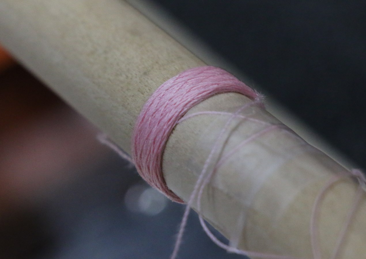
I will talk about this more later, but for now I simply have a teaser picture of the coil winder under construction.  Files for the 3D-printed 3-jaw chucks came from thingiverse.com, but everything else is my own design done in Fusion360.  I won't know if it works until it's done, because I have found almost no information on the intertubes.  All is subject to change.  But the second picture shows that the universal/honeycomb portion is working, at least if your goal is to print inductors made from pink thread.

[edit]

Description:

1) Foreground crank is for winding; the right crank turns the lead screw for fine-tuning the start position.

2) The bevel gear on the end of the crank shaft is fixed at 39 teeth.

3) The bevel gear on the chuck shaft is changeable with 38, 40, 42. and 44 tooth (shown) options.

4) The bevel gear ratio sets the winding angle of the helix.  The 39 tooth odd gear ensures that subsequent wind layers do not stack directly on one another.

5) The linear cam on the crank shaft was designed to maintain a constant chord length through the diameter at any angle.  This allows the use of push-push ball bearing followers so that a return spring is unnecessary.  The stroke is 1 inch.

6) The two arms with the dumbbell-shaped link between them allows infinite adjustment (by moving the link position) of the reciprocating stroke from zero to one inch.

7) The lead screw moves laterally on linear ball bearings.  All wear points are either ball or brass sleeve bearings.

8) The large gear in the foreground and the spur gear at the hub of the drive chuck are part of the yet-to-be-completed progressive drive train.  As the chuck rotates this motion will be transmitted through a gear train (not yet designed) to the large gear, causing the lead screw to rotate and in turn causing the feed arm to translate left or right. There are two linear bearings in the gear that allow the lead screw to rotate while freely moving laterally.

9) The feed arm shown is temporary.  The final one will have wire guides, and roller above the piano-wire feeder, and a friction tensioning knob at the base.

10) The aluminum tray was originally intended to be a protective pan for when shellac or other bonding liquid is applied to the coils. I decided to make it the dovetailed tailstock guide rail as well.

11) In the incomplete state shown the winder operates in universal mode only.  As the crank handle is turned the cam pushes the follower plate left and right.  A ratio of this linear stroke is transmitted to the lead screw so that it moves laterally with every rotation of the crank.  The feed arm contains two brass half-nuts that rest on the threaded rod, held in place by magnets.  This allows the arm to be picked up and moved to the desired spot without having to turn the small crank a bunch of times.

12) There is a magnet embedded in the wheel above the counter module to trigger a sensor, but I'm going to replace this all with a cam an a small mechanical counter.  The counter shown takes up too much space that I want to leave available for the possible addition of a variable speed motor.

13) The wire spool will be supported on a roller tube at the lower back of the base.  The wire will feed slightly above the base and over the metal tray to the base of the feed arm.  This will keep the wire out of the way of the action.

I'll post more pictures and a video when it's done.

Posted: 11/12/2020 1:28:35 PM
dewster

From: Northern NJ, USA

Joined: 2/17/2012

Beautiful Roger! 

It looks like:
1. You turn the hand crank in front to do the winding, and the hand crank on the side is for the initial donut position.
2. A bound cam sitting on top of a small linear rail does the reciprocating, and the ratio is 1:1 for hand crank and cam rotation.
3. Those two reciprocating arms have an adjustable tie point to vary the width of the donut.

Unsure:
4. Do you change the winding / reciprocation ratio via those 90 degree gears in the back?
5. What does that big gear up front do? 
6. Where is the winding count sensor?

General questions / musings:
7. Is this just for ferrite core inductors?  That is, are there any non-ferrite core application that you can think of?
8. Is there an "ideal" donut geometry in terms of both inductance and self-C?  Like a single wire width spiraling out radially?
9. Might there be a self-C penalty for winding near the ferrite?  I assume there is an inductance penalty for winding too far away from the ferrite?
10. The wire going from donut to donut seems to be a bit of a non-ideality as it has to traipse down the donut face, though I guess it is so small it can't add much to self-C?
11. I wonder how much ferrite magnetization losses contribute to overall Q reduction?
12. Since the ferrite is an open rod, the core is then hugely gapped, so I'm thinking the ferrite formulation might not have all that much influence over things (L magnification, temperature dependence, etc.)?  So I wonder if its main purpose is magnifying the L of individual donuts, or does it also significantly couple adjacent donuts?
13. I believe multi-donut type RF chokes exist mainly to reduce physical size - are there other benefits, or is everything else a compromise / wash (if done well)? 
14. Historically, I wonder when these types of chokes came into existence, like if Theremin could have used them in his designs early on.  Certainly Bob Moog took advantage of them, and he used a "meta" arrangement of several in series for EQ, which I imagine lowers overall self-C even lower.

[EDIT] Sorry, not trying to beat you up with questions!  And I know it's early in this project so ignore me.  Thanks much for the added explanation above!

Posted: 11/12/2020 1:45:50 PM
JPascal

From: Berlin Germany

Joined: 4/27/2016

This is a great project for theremins, high Q LC circuits and the temperature stability of oscillators! Since years I looked for high inductive air core coils. Now I have some and am very happy with it.

Can you make with your machine coils, low capacitive due to serial connected for example, upto some mH? 

Posted: 11/12/2020 2:12:24 PM
pitts8rh

From: Minnesota USA

Joined: 11/27/2015

I hope I answered some of the questions with the description that I added while you guys were posting. I have much to learn about the machine and about the electrical effects of various winding patterns.  I haven't found a great deal of information out there, probably because the peak period of use of RF inductors precedes the internet.

Although my first goal was to be able to wind my Melodia coils,  I am really driven to try to reduce the size of the D-Lev inductors while still maintaining the best performance possible.  Large single layer air inductors really cramp your style when it comes to packaging.

Posted: 11/12/2020 3:47:39 PM
dewster

From: Northern NJ, USA

Joined: 2/17/2012

"I haven't found a great deal of information out there, probably because the peak period of use of RF inductors precedes the internet."- pitts8rh

The best papers I found were by David W. Knight, who seems obsessed with nailing things down to the last decimal place.  His work is mostly with single layer air core solenoids though.  The exact origins of self-C seems to be something of a mystery.  ILYA will probably disagree with me, and I could certainly be wrong, but I think there is very slight inter-winding C due to the slight phase difference between them, and it adds up.  There is also self-C just from having the two ends nearer to each other in a physically small coil.

I'm still somewhat stymied by why Theremin made his coils so freaking tall, aspect ratio wise.  I'm sure they work really well, and he was certainly no dope, but his coils don't make 100% sense to me, which leads me to wonder if he was limited by coil form dimensions, or wire diameters available to him, or something.  His coils made his expensive wooden cases relatively gigantic, so he must have been very aware of it.  Perhaps he was enamored with the podium style, and the natural "ovenization" the enclosed volume imparted to his circuitry?  I dunno...

"I am really driven to try to reduce the size of the D-Lev inductors while still maintaining the best performance possible."

I'm stating the dead obvious, but the first line of attack / defense here is using the absolute finest wire you can possibly stand without tearing your hair out.  DCR doesn't seem to have much effect on Q.

Posted: 11/12/2020 5:50:50 PM
pitts8rh

From: Minnesota USA

Joined: 11/27/2015

"ILYA will probably disagree with me, and I could certainly be wrong, but I think there is very slight inter-winding C due to the slight phase difference between them, and it adds up. There is also self-C just from having the two ends nearer to each other in a physically small coil."- Dewster

Just to be clear, inter-winding C is a function of the the physical attributes of conductors and dielectric between them and is independent of voltage unless you want to consider extreme cases where the voltage can affect the dielectric or the physical spacing. Inter-conductor capacitance between conductors of the same potential isn't relevant, but of course when there is a voltage gradient across the C as you describe the capacitance can no longer be ignored. This is why the even-mode impedance of a pair of conductors is higher than the odd-mode impedance, sometimes approaching infinity if the conductor pair is far from ground.

You are correct that you have capacitance between adjacent windings and the ends of the coil, but you also have capacitance between non-adjacent turns as well, and the detailed schematic of a simple coil gets very complicated.  You obviously have to keep the ends of a coil separated, but you also want to make sure that adjacent windings never run parallel to one another for a very great distance.  So the question becomes how to pack as many turns into a given volume while keeping all the inter-conductor capacitances at a minimum.

If you look at one section of the Miller/Hammond/Bourns style of multi-section inductors, you will see how this works.  The helical wind is staggered to provide an air space between adjacent turns. When layering begins and the wire starts stacking on top of other windings, it crosses the underlying wire at an angle, minimizing the capacitance.  The narrow width of the coil ensures that you don't get many turns of wire shunted by the capacitance with the layer above it. And the larger diameter of the section compared to the width helps prevent shunt capacitances from bridging a significant number of turns.

When the section gets too large to be physically practical you begin a new section, taking care to keep the start and end wires of the previous section separated.  The space between sections further minimizes bridging capacitances.  And the big benefit of these pi-wound coils is that by going muti-layer with minimal parasitics you get the nice size reduction over a single layer coil.

It's interesting to note that if you look at the schematic model of a real inductor,  modeled approximately as a string of small single-turn series inductors alternating with small inter-winding shunt capacitances (ignoring the secondary parasitics), the model starts to look just like the lumped-element approximation of a distributed transmission line. This is where the world of lumped-element models and distributed-element models converge.  The real-world inductor is really a transmission line, and when you pump one end of the coil at its self-resonant frequency with the other end open, it behaves like an open-ended quarter-wave section of a transmission line.

Back to the relevant subject, I am hoping that there will be some satisfactory coil winding pattern that will yield high Q millihenry air-core inductors that are substantially more compact than the PVC single layer coils.

"I'm still somewhat stymied by why Theremin made his coils so freaking tall, aspect ratio wise. "

I haven't seen any good pictures of his coils, but if he was using cotton or silk insulated wire that might require a lot of volume.  If he was using fine wire there is probably more insulation than copper on the coil. Adding length to make up for it isn't ideal but would you really want to make the coils any larger in diameter?

Posted: 11/12/2020 6:47:21 PM
dewster

From: Northern NJ, USA

Joined: 2/17/2012

"Back to the relevant subject, I am hoping that there will be some satisfactory coil winding pattern that will yield high Q millihenry air-core inductors that are substantially more compact than the PVC single layer coils."  - pitts8rh

One could perhaps do an "inside out" RF choke, instead of donuts do concentric single layers with some sort of insulator in-between.  Or do a combo of this, donuts made of concentric single or multi-layer Pi windings.  Electrically connecting each concentric ring might be a practical problem though.

With donuts or separate inductors in series not sharing significant coupling, it seems that one would be dramatically reducing self-C just by keeping the phase shift across each element low.

"I haven't seen any good pictures of his coils, but if he was using cotton or silk insulated wire that might require a lot of volume.  If he was using fine wire there is probably more insulation than copper on the coil."

Yes, I think the wire insulation thickness explains a lot of Theremin's coil geometry.

"Adding length to make up for it isn't ideal but would you really want to make the coils any larger in diameter?"

I would!  Anything significantly over 1:1 starts to really cut into inter-winding coupling, a magnifying factor, and you end up using more wire for the same inductance value.  So increasing the former diameter somewhat can significantly reduce the length.  And there's Pi, so per turn wire length is >3 times the former diameter, and inductance is highly correlated with total wire length.  I can see going 2:1, but not 4:1 or whatever he was doing (in an ideal world).  Perhaps he was just trying to get the business end as far away as possible from the metal chassis, but I think I would choose to elevate the bottom end instead of increasing the aspect ratio.

Roger, have you played with the inca program at all?  It can give a lot of insight into inductance geometry and coupling.  It probably can't do Pi-windings, but you might be able to fake it somewhat.

Posted: 11/12/2020 6:48:42 PM
Henk Brand

From: Schiedam The Netherlands

Joined: 12/22/2014

Wonderful coilwinder! I’ve tried to understand your working description but I hope you will post a short video of the winder in action as to see how everything is working. A few years ago when I was building my Clara Rockmore Theremin I was faced with the problem how to wind the big coils and so I had to built my own winder from all kind of scrap parts and an old electric handdrill who was regulated by a variac. Counting the number of turns (1600) was done by a little magnet and a modified pocketcalculator. You can see a Photo in the Photo albums on page 3 ( Clara Rockmore Replica) 
(Sorry I don’t how to transfer my photos into this posts)

Posted: 11/12/2020 7:40:50 PM
pitts8rh

From: Minnesota USA

Joined: 11/27/2015

Henk-

Just right-click on the image in your photo album (the big one, not the thumbnail) and select "Copy Image Location".
In your post select the "Insert an image" icon from the top row, third from the right, and do a Ctrl-V paste into the URL box. Then press insert.

Here ya go... Nice coil!

Posted: 11/13/2020 10:03:17 AM
Henk Brand

From: Schiedam The Netherlands

Joined: 12/22/2014

Thank you Roger for helping me out! I really want to see your coilwinder working when it’s finished. although I have a few Miller Pi-coils left I surely would like to be able to wind them myself so I am anxious to know how you accomplished this. 

You must be logged in to post a reply. Please log in or register for a new account.