Claravox teardown

Posted: 11/12/2021 9:17:04 PM
Flounderguts

Joined: 10/24/2020

Well, apparently ContraDude and Dewster have had the chance to peek into a Claravox, to solve the pernicious volume antenna issue...but I missed out on that. I've been meaning to do a teardown, but between life and actually playing the Cvox, it hasn't happened. 

But today, I finally got around to ripping it up a bit. I took a lot of pictures, and it's neither as delicate as it seems, nor as complicated to take apart. 

Some things that are useful to know:
1. the front and back "fabric" panels are plastic. Probably pretty hard to damage, and the covering is a paper that is glued on. By hand. Looks like a tedious job!
2. The headphone jack, power switch, and IO panel on the back are all on their own little PCBs. That means if you knock your Cvox over and rip the headphone cord out, it doesn't damage the main PCB. That's a good thing!
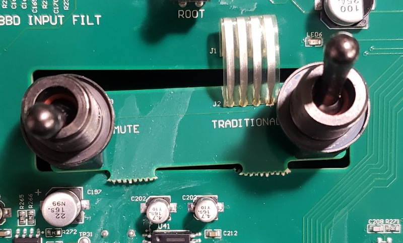
3. All the potentiometers and switches are through-hole...again, good for repairs! They are all Taiwan Alpha brand, with the exception of the fancy mute and traditional switches, which are Carling 2M1H fully sealed toggles. 
4. There are 54 designated test points on the main PCB!

I don't want to clog the forum with embedded photos, so I created a Google Pix album that is public. Here is the link:

Claravox teardown album

There are about 55 pix, and I will be adding more as I get into the antenna pcbs and the pitch arm coil. The PCB pix should be good enough to see the markings on the individual IC's.

Posted: 11/12/2021 9:36:02 PM
Flounderguts

Joined: 10/24/2020

I'm in the process of examining the PCB, but here are some initial takeaways...

first thing I spotted were the Xvive audio MN3005 bucket brigade delay chips. Very cool choice! I have some of these in my homebuilt contact mic synth. 

The rotary switches are mounted at interesting angles, don't you think?

Bazillions of test points, and the sections of the theremin are nicely labeled. You can clearly see areas of 17V, 15V, 10V, 5V, and 12V as well as -12V. 

TMS320 Piccolo MCU...these are unobtanium at the moment, and TI puts the lead time for more at late 2023. This $20 chip is possibly one of the reasons Claras have been delayed so much. 

unpopulated JTAG and AUX (??) headers...veeeery interesting. 

A few unpopulated pads...C269,  C312, VR7, C17, R149, R403, R402, R8, C147...and a whack more! In fact, almost every section has unpopulated components. There could be a very interesting story here...I'd love to take a peek inside a pre-production Claravox! I'm guessing they made significant hardware changes. 

There's a SS2164 hiding out in the VCA section

There is a trimmer that is accessible from the inside of the instrument that is next to the vol antenna plug. Hmmmmm

Posted: 11/13/2021 2:52:02 AM
dewster

From: Northern NJ, USA

Joined: 2/17/2012

Thanks for that Flounderguts!

I wonder if the above has anything to do with why many are experiencing mute lockup?  I suppose they did that to offset different depth controls.

I'm amazed at the sheer amount of random circuitry on this mammoth PWB.  I figured it was mainly there to save labor wiring up the controls, with a harness leading off to a DSP or ARM or something, not this.  Totally didn't expect this level of jellybean city.

Posted: 11/13/2021 3:31:26 AM
Flounderguts

Joined: 10/24/2020

Those Carling toggles are pretty robust, and sealed. The breakaway bit of pcb with the ribbon is a bit odd, but the soldering is robust. When you pull it apart, there are also two massive thick washers spacing them back, to prevent the massively long bushings from poking out too far. Honestly, I'm surprised they didn't use pushbuttons or rotary switches.

I think the mute lockup has more to do with when the instrument is in "quantize" mode...that whole thing is a bit wacky. 

You're right, though...it does look like a dev board that was put into production. It looks easy to repair stuff, tho!

Posted: 11/13/2021 4:33:01 PM
dewster

From: Northern NJ, USA

Joined: 2/17/2012

"The rotary switches are mounted at interesting angles, don't you think?"  - Flounderguts

I guess that's to align the shaft flat with the knob pointer and panel lettering.

"TMS320 Piccolo MCU...these are unobtanium at the moment, and TI puts the lead time for more at late 2023. This $20 chip is possibly one of the reasons Claras have been delayed so much."

I haven't even peeked at the datasheet, but why use a DSP when there are multi-core GPU / SoIC offerings out there in droves for less $?

"A few unpopulated pads...C269,  C312, VR7, C17, R149, R403, R402, R8, C147...and a whack more! In fact, almost every section has unpopulated components. There could be a very interesting story here...I'd love to take a peek inside a pre-production Claravox! I'm guessing they made significant hardware changes."

That's a little disturbing in a production unit, though Moog Inc. seems to be saying that they won't be making any more, so why tidy things up I guess.  When the bean counters start to get restless, put on a blindfold and randomly poke your finger at a calendar (i.e. modern management best practices) and call a halt to development on that day - what you get is what you get (in this case a flurry of returns).

"There is a trimmer that is accessible from the inside of the instrument that is next to the vol antenna plug. Hmmmmm"

Hmmmm

"Honestly, I'm surprised they didn't use pushbuttons or rotary switches."

Going for that retro look IMO. 

(The D-Lev external mute input used to be for an external state holding switch like a toggle.  It's now an active low momentary input so as not to produce more than one state holder (the software) so you can parallel as many NO pushbuttons as you like without any conflicts or user confusion.)

"I think the mute lockup has more to do with when the instrument is in "quantize" mode...that whole thing is a bit wacky."

Could you elaborate?  I've read some folks complaining that quantization exacerbates field noise, which sorta makes sense I suppose as the pitch field gain is increased between notes.  But I haven't read anything about the mute lockup issue being associated with quantization.

Posted: 11/15/2021 4:08:51 PM
Flounderguts

Joined: 10/24/2020

I updated the album a bit...pix of the volume antenna board. There is another unobtrusive trimpot on that board, making a total of 3 antenna adjustment points. Also the Pitch antenna board (complete with added wire!) and the headphone and power switch breakout boards.

As for the mute lockup with quantization, it's an issue that I first saw reported on Facebook, I think in the Theremania forum...? At any rate, I've been playing with it, and if you hit the quantize button, but don't follow through with a scale selection and keep playing, the mute won't work. It's an odd bit of workflow, and I think the main takeaway is that even though the mute is a toggle switch, it is not disconnecting an audio circuit, but instead changing a digital state, which in turn modifies the audio path. 

I wonder why they settled on those particular toggles...they could have found some big funky brass toggles to match the antenna, or even a brass plated cap for a tact switch. 

The brass plates on the outside of the theremin are double sided. This is a really important bit of information...it means that a Right Handed instrument can easily be converted to Left Handed, and vice versa! That is because the brass plates, which index the antennas into place, are countersunk and can be mounted mirror image. That will put the pins for the pitch antenna in the proper spot, and same for the volume, although I'm not sure if the pin would have to be re-drilled or positioned to get the antenna angle just right. 

Also, I was hoping the antenna sockets would be an off-the-shelf part but it seems to be a Moog-specific mold, and the ejection-pin marks match the ones on the panels...indicating that they were probably made at the same facility. The antenna screw also contacts the brass plate, so it seems to be part and parcel of the sensor area. I was a bit surprised that the plate wasn't isolated, but there ya go!

Posted: 11/15/2021 7:51:58 PM
dewster

From: Northern NJ, USA

Joined: 2/17/2012

Thanks again Flounderguts!  Looks like they added some splooge to the RF chokes (top/bottom = before/after):


Posted: 11/15/2021 8:02:29 PM
Flounderguts

Joined: 10/24/2020

Huh! and some of the vias seem to be filled on the pic you supplied...

Posted: 11/20/2021 10:44:42 PM
Flounderguts

Joined: 10/24/2020

Updated the album again...took apart the pitch antenna arm. 

The whole thing went back together EXTREMELY EASILY. This is by far the easiest theremin I have ever had the pleasure to disassemble and assemble. There seems to be plenty of places to mod and hack the theremin, should it ever become necessary. And it seems like reprogramming it could also be a doddle, from a hardware perspective. 

I am impressed with the wood pieces and joinery, even if I am less impressed with the brasswork. I wish that they had taken the time to make sure that all the knobs sat on the shafts at the same height, but I think a little trimming will be easy for the OCD knob people. I may do it on my instrument, if only to assuage the itch of knowing exactly how much to remove!

My next project will be working on some lighter weight replacement antennas (probably gold-anodized aluminum) and getting proficient with the software. 

Because the panels on the front and back are so simple, I think it would be pretty straightforward to fab ones out of other materials, such as aluminum or wood veneer. Furthermore, it seems like an overlay or alternative panel facing would be a fun project. If I had been smart, I would have measured the panel for a DXF or AI file showing the location of the knob holes and edges!

One of the things about performing with theremin is the relatively uninteresting instrument placed between you and the audience. There is a ton of space inside the Claravox, and a big panel facing out...I wonder what creative ways we could use that to help engage the audience? Beyond a bunch of blinkenlight, I mean...

Posted: 11/21/2021 5:25:54 AM
bendra

From: Portland, Oregon

Joined: 2/22/2018

Thanks for the pictures, that's really good stuff! Probably a stupid question, but is there a good reason for Moog to put the big coil in the hollowed-out pitch arm? As you indicate, it's kind of a complicated cutting job to get it in there, so I assume having it there must have some advantage. It surely would have been much easier to just have it inside the cabinet with the rest of the electronics

You must be logged in to post a reply. Please log in or register for a new account.