DIY Etherwave Theremin inductors replacement

Posted: 9/14/2024 8:20:06 PM
oldtemecula

From: 60 Miles North of San Diego, CA

Joined: 10/1/2014


The squeaky wheel always gets the grease. I posted my Stock research to show I have nothing against digital programing or digital synths imitating a piano or a theremin.

The original poster is building an analog theremin and was asking about coils. Hopefully from this thread he learns that what's important is how the three oscillators interact fully exposing the Theremin Phenomenon.

I built a theremin using vacuum tube oscillators with the resonating pitch antenna and the results were the same as using transistor but slightly better in sound as tubes have a slower roll over of the sine wave for a deeper more natural vocal sound.

https://www.oldtemecula.com/+smooth2-4.mp3

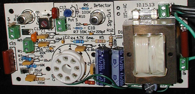
I used two of these oscillator seen in the image, notice nothing special about the coil I used. I can only sweep the pitch field, nothing more. The first time I heard my theremin design sing musically is after I sent it to St Petersburg Russia, the home of Lev Sergeyevich Termen.

For myself the finest analog theremin performance ever performed was by Peter Pringle though he does not like it. Probably mad when I post it. This is his Hoffman theremin the same one that created the sound effect in the original 1951 “The Day the Earth Stood Still”.

https://www.oldtemecula.com/+aranjuez.mp3


I wish you all the best as time is only borrowed.

Christopher


Posted: 9/15/2024 6:34:09 AM
ILYA

From: Theremin Motherland

Joined: 11/13/2005

Back to variable inductances.

A DIY theremin cannot be considered as "DIY" unless it uses DIY coils. Just kidding.

What are the difficulties in winding the coils manualy?

It only takes about fifty turns.
The coil core can be taken from old AM radio (some coils have a built-in capacitor, which will have to be desoldered or carefully destroyed).

Any RLC meter + a piece of thin wire (can be taken from a transformer or relay).

The link to my design with DIY coils.
Sure it's not a problem to use an online translator.

Posted: 9/15/2024 1:58:21 PM
dewster

From: Northern NJ, USA

Joined: 2/17/2012

"Back to variable inductances."  - ILYA

Oh, come on man, tips on how to play the stock market are totally related to Theremin coils! :-)

"The link to my design with DIY coils."

Ah, there we go, the perfect response to the OP (and me!) - thanks ILYA!

Your hand wound EQ coils interest me in particular.  Looking at the winding directions and dimensions, I'm trying to replicate them in my tcoil software:

/*
> choke: awg[39], fd[11.5]mm, ow[20]turns, o[12]donuts, oo[3.82]mm, f[260]kHz, l[26.3]mH, file[etherway_pitch]

  Type            CHOKE
  L total          26.3 mH
  N total          2935 turns

  Wire Length      117.4 m
  Wire AWG            39
  Wire Cu Dia    0.08969 mm
  Wire OD        0.1009 mm

  Form Dia          11.5 mm
  Turns OD        14.12 mm
  Turns Width      44.04 mm
  Turns W/OD      3.118 (aspect)

  Donuts              12
  Donut N          244.6 turns
  Donut Height    1.311 mm (13)
  Donut Width      2.017 mm (20)
  Donut H/W        0.65 (x-section)
  Donut Gap        1.803 mm

  L Mutual        26.18 mH
  L Self          0.1242 mH
  L M/S            210.9
  L/Wire Len        224 uH/m

  DCR              312.2 Ohms
  Skin                1
  Proximity            1
  ACR              312.3 Ohms @ 260 kHz
  LR Q            137.6 @ 260 kHz (CAUTION: NO SELF C!)
*/


The individual donut winding widths weren't given, nor the donut separator widths, but going by the overall length of 44mm / 12 donuts / ~1.5mm winding height produced the above (donut width=20 turns=2mm; spacer width=1.8mm).  Scrambling the windings rather than having neat layers would change things somewhat, but it's all reasonably close.

The calculated Q is overly optimistic though, did you ever measure the Q of your coils with the antennas attached?

Posted: 9/15/2024 7:54:09 PM
ILYA

From: Theremin Motherland

Joined: 11/13/2005

The spacer was planned to be 1mm thick (plus 2.75 mm of widing heigh), but in fact it has an uneven thickness (slightly thicker at the base and slightly thin at the end).

I turned the coil core on a lathe using a homemade "comb" cutter.

And no, I didn't measure the Q, just the DCR and SRF.

Does your model  calculate the SRF?

And why DCR=ACR?

Posted: 9/16/2024 12:07:36 PM
dewster

From: Northern NJ, USA

Joined: 2/17/2012

"And no, I didn't measure the Q, just the DCR and SRF."  - ILYA

Without ferrite, I'd take a wild guess that the Q is probably less than 100 @ 260kHz.

"Does your model  calculate the SRF?"

No, unfortunately.  Self C requires really complex calculations, and it's a rather contested field.

"And why DCR=ACR?"

There's no appreciable skin effect for 0.1mm diameter wire at 260kHz, which is kinda related to proximity effect (eddy currents within the wire).  The ACR is generally a low ball for my tool, hence the caution.

The highest Q I've seen is 188, and that was for a 1.7mH single layer solenoid with heavy build 32AWG wire insulation.  The Bourns 6310-RC (s 50mH 3 donut ferrite choke) is around 136.  The D-Lev kit coils are around 180.  These are all with a nominal 13pF or so load of the jig.

I'm wondering how important Q is for an analog Theremin, particularly for the linearizing function?  Your explanation of this in the Etherway article is the best I've seen!

You must be logged in to post a reply. Please log in or register for a new account.