


Hi again,
So I checked Q3 and i don't get the right values: source pin= around 3mV, gate pin= -12.6V, drain pin = 5.7V
For the coil T3 i have around 30 Ohm between 4 and 6, 32 Ohm between 1 and 2, 32 Ohm between 2 and 3.
I got an infinite resistance between 4 and 2, 4 and 3, a very low resistance between 4 and 1
and also inifnite resistance between 6 and 1, about 27 Ohm between 6 and 2, and 60 Ohm between 6 and 3, these value are not quite stable.
I ordered some 2N5484 and i'll see if it solve the problem, I was looking for an IF transformer like T3 but it's a bit hard to find, do you have any idea?
Thanks again.
Diagnosing Jaycar/EPE/Silicon Chip/Kees Enkelaar Theremins
Posted: 10/6/2014 8:23:26 PM
Posted: 11/9/2014 7:32:23 PM
This seems to be the place for jaycar answers, I might even have asked about it before as I abandoned it quite some time ago.
Ive got a MK2
Issue is as long as Im touching (or grounding to a large piece of metal) a certain point, it works perfectly.
If I dont the volum coil doesnt oscillate and theres just a low sound in the background when I tune (if that).
That point is at the last resistor before ground (and BC548) in volume section, possibly if I touch base of 548 as well, havent tried to fit my finger there ;)
Ive changed pretty much everything around there, dont really know how to continue.
Help?
Posted: 11/16/2014 3:19:09 PM

Thanks for all the great site & information. It has given me lots of late night reading.
My wife asked me what I wanted for my birthday...."something you wouldn't normally get for yourself" she suggested, I mentioned the Jaycar Theremin MkII as something I keep seeing at their retail outlet and always thought it would make an interesting project ....to my delight I was given the kit for my birthday. after putting it together everything worked.
So I've been adding the Jaycar MkII suggested mods. with great success....everything has worked and tested out fine , the control over adjustment is much improved......almost finished and a box constructed.
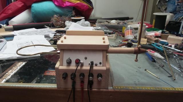
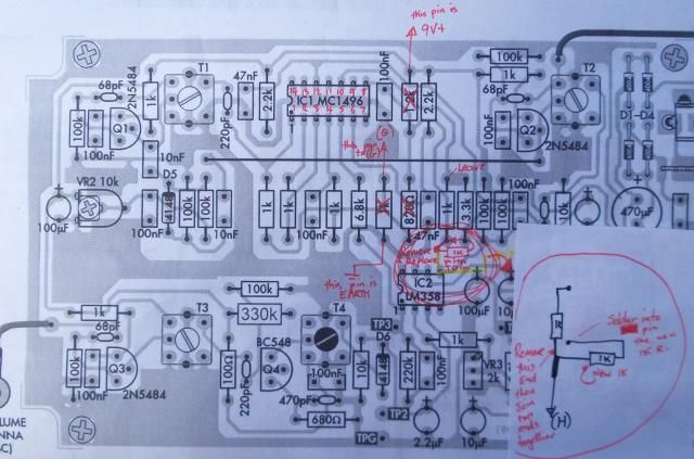
Took me some time to translate the schematics to the printed circuit board and after a bit of brain drain I worked it out. *see pic
.....HOWEVER.....I've struck a snag.
Every thing was working when the dog gets under my feet and pull every thing of the work bench....Aghhhh! now I have no pitch variation. I have continuity in the antenna. There is control over the volume loop but the hifi amp. must be turned up very high for sound to be audible.....I've checked all soldering under a 3x loupe and found only one suspect joint and no loose wires....
TP 1, 2 &3 all give correct values and can be adjusted via the new mods. I not an electronic guru...just able to follow the plan so, any help as where to start with the problem solving would be appreciated.
Posted: 11/18/2014 11:14:09 PM

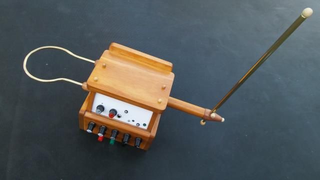
@gizmo, nice woodwork on your theremin. looks quite sturdy. however, they just are bad in aerodynamics. and a pain to troubleshoot them. i suspect the if-coils ,t1-t4, they are quite sensible on brute forces and might be out of tune. the small ferrite screw might me whacked. try to retune them a bit, or completely. but don't use too much force,make sure they are not broken specially after a drop. but it might be also everything else, like broken pot or chip out of the socket for expl. thierrys detailed step by step guide might help. good luck. btw, was it turned on, when the dog pulled all down?
Posted: 3/14/2018 7:16:05 AM
Hello Thierry. My name is Dave and I am from New Zealand. My daughter bought me a Jaycar theremin mk2 kit for my 62nd birthday. She always gives me excellent presents. I have soldered all the parts together but I have no sound. I do not yet have a frequency counter, but I have a 20 MHz analog oscilloscope so I have been able to follow your instructions to discover something. I hope you can help me to understand what is going on.
pin 1 of mc1496 is oscillating at about 400 KHz at 1 volt pp.
pin 10 of mc1496 is oscillating at about 500 KHz at 0.5 volts pp.
when I initially measured the base of q4 it was oscillating at about 450 KHz at about 1.3 volts pp. While the oscillation of pin 1 and pin 10 were nice sine waves, I noticed that the oscillation at the base of q4 had a little notch in it. Then, after trying to adjust frequencies using T2 and T3 (as you described) I noticed that there was no longer any oscillation at the base of q4. It had stopped oscillating. I suspect that the notch I noticed previously might have been a sign of impending failure of a component.
Also, I have 9 volts between TP1 and ground, 2.5 volts at TP1, both as stated in the instructions, but there is only 0.03 volts at TP3, not 7 volts as stated in the instructions and not adjustable. There is something wrong there but I don't know what it is.
I hope someone might be able to help me understand how to proceed. Thanks, Dave.
Posted: 3/14/2018 9:46:40 PM
I think my results indicate that there is a fault in the volume antenna circuit. My limited understanding tells me that there should be an oscillation detectable at pin 6 of T3, but there is no signal there. This made me think that it is the circuit around Q3 that is at fault. Based on a comment earlier in this thread I thought the JFET might be faulty so I took it out and tested it. It tested ok. All I can think of to do now is to buy and install a new JFET despite my tester saying it's ok.
Posted: 3/14/2018 11:52:58 PM

Hello Dave,
Thierry is the master, there has never been anyone smarter in theremins in my opinion. I've done a little trouble shooting and do not have your schematic but think the two oscillators should be operating at the same frequency. Right now the audio is at 100 khz which is beyond human hearing. The audio frequency of the sound is the frequency difference of the two oscillators. They are both working so you are really close to success.
T
Posted: 3/15/2018 6:23:35 AM
Hi Touchless. Thanks for your reply. The two pitch antenna oscillators are working but it is the volume antenna oscillator that is not working so there is no sound. I have bought a replacement JFET for the volume oscillator circuit so I will try installing that tomorrow. Dave.
You must be logged in to post a reply. Please log in or register for a new account.