Let's Design and Build a (mostly) Digital Theremin!

Posted: 5/13/2012 9:03:20 PM
FredM

From: Eastleigh, Hampshire, U.K. ................................... Fred Mundell. ................................... Electronics Engineer. (Primarily Analogue) .. CV Synths 1974-1980 .. Theremin developer 2007 to present .. soon to be Developing / Trading as WaveCrafter.com . ...................................

Joined: 12/7/2007

MIDI is too slow and innacurate for theremins.

I am not thinking primarily about outputting CV to analogue synths - IMO, Thereminists do not have the free hands required to make use of an external synth..

I see the main use of CV as a way to enable precise control over register and span - to allow the thereminist to play a 3 octave 'Claramin' or a 7 octave tVox, or a register selectable E-Pro, or a 5 octave EW - all contained in one instrument....

I believe that combining control over heterodyning circuits and 'conventional' synth modules (particularly VCF's) opens the potential for achieving a universal theremin..

But - For me, implementing this dream is probably way over any possible horizon.. All I can do is talk about it and probably bore everyone to tears! LOL!

Fred.

Posted: 5/14/2012 2:55:24 AM
dewster

From: Northern NJ, USA

Joined: 2/17/2012

"I see the main use of CV as a way to enable precise control over register and span..."

I guess I'm not seeing a big upside to the DA / AD conversion and everything in between.  Analog like that is analog computing - why not just do it with numbers?  I have nothing against analog per se, but these days it is mainly for the rich retro movement buying class.

Posted: 5/14/2012 11:59:02 AM
FredM

From: Eastleigh, Hampshire, U.K. ................................... Fred Mundell. ................................... Electronics Engineer. (Primarily Analogue) .. CV Synths 1974-1980 .. Theremin developer 2007 to present .. soon to be Developing / Trading as WaveCrafter.com . ...................................

Joined: 12/7/2007

"I have nothing against analog per se, but these days it is mainly for the rich retro movement buying class."

Dewster - I have nothing against digital implementation - there are applications where digital implementation allows creation of products which would be unrealizable using analogue.. And it MAY be that the theremin is ready for this approach, and that you can achieve a high-end theremin using digital technology which would be producable at lower cost than an equivalent analogue implementation... Having seen your video now, I am quite impressed!

And yes - certainly for mass production, digital can be the only practical way to go - primarily because analogue usually requires a lot of engineer time to calibrate the instrument, digital has this big advantage.

So, first and foremost, please understand that I am in no way trying to put you or your efforts down - I think that what you are doing is exciting and laudable, and that regardless of what eventually comes from it, you are adding greatly to the pool of knowledge which inspires future improvements and developments.

My first ventures into theremin development were a mix of digital and analogue - I was using PSoC parts which contain configurable digital UM's (in many ways similar to FPGA, but not quite as versatile) and configurable analogue UM's (which are quite impressive, and include amplifiers, D/A, A/D, and a switched capacitor UM which can be configured as capacitance sensing block, filters etc).. and an 8 bit microcontroller with access to the UM's.

The main dissadvantage of the PSoC was the MCU - it was not fast or powerful enough to do any serious real-time computation (the latest ARM based PSoCs are much faster, but I have not played with these - they appeared too late, and I had changed direction by then - I may return to at least evaluate these some time soon).. The (original) PSoCs just missed the mark for my applications - there were not enough UM's to implement everything without some of the tasks being handled by the MCU, and the MCU was not powerful enough to handle the required tasks. In particular, I was not able to obtain high enough resolution on the capacitance sensing fast enough (I could get 'adequate' resolution with a latency of about 20ms, but this hogged most of the MCU's resources, and correcting for linearization and exponentiation with the remaining resources added another 20-30ms, putting the latency way outside of what was acceptable )

I say the above so that you understand that I am not "anti digital" per-se, I have dabbled with it, and I can see the advantages of it - and perhaps if I had managed to obtain the results I was seeking, I would have religated analogue to a few peripheral functions.. as things styand at present, I lhave religated digital to a few peripheral functions, LOL!

I must also state that I have a severe "disability" when it comes to maths intensive programming - I am mathematically dyslexic! Oh, I can do complex maths, but it does not come natural to me - I look at some of the exchanges here and on E-14, and it can take me an hour to decode one line of formulae.. I got another engineer to write the PSoC code to get the exponential from the capacitance value in the PSoC.. So this probably biases me away from using DSP's

And then, there is the SOUND..

I own several synthesisers - Old Roland Juno with digital oscillators and everything else analogue, which sounds great.. Moog Prodigy and Akai AX73 which is are analogue, and sound great, A Korg Karma which is all digital and sounds bloody marvelous, and several digital modules including the Access Virus which is supposed to be an analogue emulation, which all sound 'digital'.. I think it is when one is trying to produce an analogue lead sound, have a lot of portamento or pitch bend, that the difference between a digital and analogue synth really shows.

It was the realization that (for whatever reason) changing pitch was where analogue sounds (to my ears) best, and the fact that theremin pitch is always dynamic, which has convinced me to stay (at least for now) on the analogue path when it comes to theremins.

Posted: 5/14/2012 12:40:14 PM
FredM

From: Eastleigh, Hampshire, U.K. ................................... Fred Mundell. ................................... Electronics Engineer. (Primarily Analogue) .. CV Synths 1974-1980 .. Theremin developer 2007 to present .. soon to be Developing / Trading as WaveCrafter.com . ...................................

Joined: 12/7/2007

Question:

My understanding is that you have a digital PLL being used for both 'reference' and 'variable''oscillators'..

I do not know how you are doing this, but if it is possible to output these two frequencies independently (as in, not derive the 'difference' but simply output one constant frequency reference square wave, and output the variable frequency (reference frequency +/- difference frequency) then I can give you a simple circuit with which you can produce triangle and ramp waveforms..

In fact, the circuit I have in mind uses logic - so could probably be incorperated in the FPGA.. I have this circuit implemented in one of my mixed-signal theremins.. I feed it reference and variable oscillator square wave signals, and it gives square, ramp and triangle waveforms out at the difference frequency - and these waveforms are at constant amplitude over the full frequency range.

Also.. If it is possible to output reference and variable frequencies multiplied by a constant value (say 8 or 16 times) then I have a simple way to generate a 1V/Octave CV from these signals.. This voltage could drive a VCF which, fed from (and tracking) the audio output would (using subtractive synthesis) give great control over harmonic content / waveform.

Let me know if you are interested.

Fred.

Posted: 5/14/2012 2:51:00 PM
dewster

From: Northern NJ, USA

Joined: 2/17/2012

"So, first and foremost, please understand that I am in no way trying to put you or your efforts down..."

Gosh no Fred, you've been quite diplomatic and understanding.  I really value your comments and insights as you've been down this road.  Thank you for taking the time to so thoroughly respond.

...I was using PSoC parts which contain configurable digital UM's (in many ways similar to FPGA, but not quite as versatile) and configurable analogue UM's (which are quite impressive, and include amplifiers, D/A, A/D, and a switched capacitor UM which can be configured as capacitance sensing block, filters etc).. and an 8 bit microcontroller with access to the UM's."

Please don't think that I'm insulting this approach, it is a very natural one to take and can be quite powerful.  But the decision to use a small processor that has slow and somewhat indeterminate response time (I realize it was forced on you in this situation) ripples back through the design, necessitating pre-processing, value storage, etc. 

I think it is best to do the very minimum necessary in the analog domain and then run screaming with the rest of the design into the digital domain.  A lot of my up-front thought in this project was to do just that.  When I see any project being digitized with A/D converters and sent to a low power uP I just have to think there must be a simpler way.

I've done a fair amount of FPGA work (in my past Telecom life) and it really suits this middle ground.  If you can instantiate custom digital structures that respond in constant time and with the speed of the system clock, a lot of design problems disappear.

"My understanding is that you have a digital PLL being used for both 'reference' and 'variable''oscillators'.."

I'm using a single digital PLL so the "beat" reference is mathematical.  Like all PLLs it has a loop filter, and within this loop filter there is a phase error accumulator (accumulated phase error = frequency error) so that quadrature is maintained over the full operating range of the PLL.  Pressing the debounced "calibrate" button registers the current NCO operating point as the new center frequency, which causes the phase error accumulator to go to somewhere near zero because there is zero frequency error at the center frequency.  This lets me use the accumulated phase error as a low-pass output of frequency, which I negate so that it increases with closer hand position, and feed to the audio NCO.

Not trying to blow my horn, but I've designed and constructed DPLLs that operate in the Telecom synchronous digital hierarchy (stratum) where all sorts of holdover, jitter peaking, wander generation, etc. have to be strictly adhered to and laboriously measured with special test equipment.  The DPLL for a Theremin is relatively simpler, though I did have to use phase dithering to make it operate smoothly, and I'd never explicitly designed a quadrature phase detector in logic.

Posted: 5/14/2012 4:22:21 PM
dewster

From: Northern NJ, USA

Joined: 2/17/2012

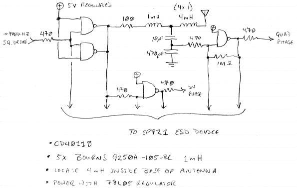
THE AFE

Above is the schematic for my present analog front end (AFE) circuit.  Here's how it works: 

The FPGA provides a square wave @ ~700kHz to the input of the two NAND gates configured as inverters.  Two gates are used in parallel here to increase the output current drive.  The current is limited by a 100 ohm resistor and then used to drive the 1mH inductor (this is mode=0 in my simulation spreadsheet).  I tried 4000UB but the drive was too wimpy and the logic too slow.  Also tried 74HC and the drive was awesome but the logic too fast

On the other side of the inductor is a capacitive divider formed by 10pf and 470pF.  The inductor mainly "sees" the 10pF capacitor because it is so much smaller than the 470pF in series, so this forms the LC "tank".

The voltage at the intersection of the inductor and 10pF capacitor is hundreds of volts, and looks like a sine wave because an LC circuit like this forms a low pass filter.  The capacitive voltage divider knocks this down to a couple of volts at the intersection of the 10pF and 470pF caps, where it is dynamically biased to ~1/2 the supply by feedback resistor 1M, and amplified / clipped by the gate to make a square wave.  This logic output, when the input frequency is adjusted for peak output voltage at the antenna, lags the input drive by 90 degrees ("quadrature"). 

The tank drive is also fed directly to a second gate, which helps to eliminate timing differences (CD4000B series devices have significant propagation times).  These two logic level outputs are then sent back to the FPGA which contains a digital phase locked loop (DPLL) that adjusts the drive frequency so as to maintain quadrature. 

The LC tank also feeds a "linearizing" inductor within the antenna, which is constructed by soldering 4 of the same 1mH inductors together in series.  The way I understand this, it is actually the resonance point of the user's hand capacitance and the antenna coil "reflecting" (for wont of a better word) back through the tank LC which is then sensed as a quadrature operating point.  There is another quadrature point located higher in frequency which works but should probably be avoided as it is less sensitive and produces less voltage at the antenna in simulation.

A Littelfuse SP721 device is used on all the I/O to reduce the chances of static blowing out the CMOS inputs, and also to protect somewhat against uncontrolled power supply sequencing.  I haven't tested this arrangement with actual static or human body equivalent ESD discharge yet.

I got the Bourns 9250A-105RC inductors from DigiKey:

L=1 mH
R=17.5 Ohms
SRF=3.8 MHz
Q=60
Isat=40 mA

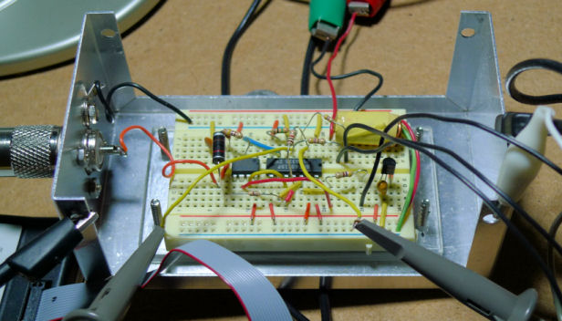
Being a prototype and all, my current AFE is constructed on a small plastic breadboard in a small aluminum project enclosure, with a standard UHF connector for the antenna (which, except for the components, are all currently available at Radio Shack, believe it or not).  The breadboard is mounted on top of a small piece of Plexiglas to space it away from the enclosure some.  Even with such sub-optimal physical design the response is good and temperature drift fairly minimal.  I'm using a 78L05 to regulate the internal 5V supply, and the 470 ohm interface resistors reduce line drive reflections (impedance match) and limit any current between the 5V AFE logic and 3.3V FPGA logic.

Posted: 5/14/2012 5:52:41 PM
dewster

From: Northern NJ, USA

Joined: 2/17/2012

THE PITCH ANTENNA

I pretty happy with the way my pitch "antenna" turned out.  It looks very much like an RF "rubber ducky" antenna.  The UHF connectors employed are so much more electrically positive and physically secure than the standard "plumbing" type connectors found on the EWS.  The connect / disconnect can be quickly and easily accomplished with no tools other than your fingers, and the presence of a ground allows one the opportunity to include all kinds of electrical elements within the antenna itself (should one so desire).  The antenna described below is designed specifically to work with the AFE of my digital Theremin prototype, and as a result may or may not be suited to other Theremins.  Though you could certainly replace the internal inductors with a solid wire and use the result as a general purpose 3/8" OD Theremin antenna.  Just keep the bottom end of the aluminum tape comfortably away from the UHF outer ground shell (say 10mm or so).

Antenna construction:

Take four Bourns 9250A-105RC inductors, trim all the leads very short except for the two end leads, which should be left untrimmed.  Solder them together in series, then solder ~400mm of small diameter solid wire to one end.  This is the inductor assembly. 

Cut a 400mm length of 3/8" OD gray PEX tubing (plumbing used to connect toilets).  Insert the inductor assembly in the base of the tube, running the connected wire through and out the top end of the tube.  Stick the tube base in a UHF connector and position the end inductor lead flush with the end of the hollow center conductor (where it will be soldered later).  Mark the position on the tube at the top of the UHF connector with a sharpie or similar, and also mark the position of the wire extending out of the top of the tube by bending it 90 degrees. 

Remove the UHF connector, and pull the inductor assembly out of the top of the tube.  Lay the inductor assembly next to the tube so that the 90 bend is aligned with the top of the tube and place a second mark on the tube indicating the location of the top most inductor.

Wrap the tube from the top down to the second mark in self-adhesive aluminum tape.  I do this the long way - i.e. the length of the tube aligned with the long dimension of the tape - so a minimum of aluminum tape is required.  You want to avoid the area at the base which will contain the inductors as this would introduce parasitic capacitance.  The white arrow in the photo above indicates the bottom of the aluminum tape.

Reassemble the inductor assembly / tube / UHF connector and again position the end inductor lead flush with the end of the hollow center conductor.  Bend the wire extending out of the top of the tube over so that is making contact with the alumimum tape on the outside and trim as necessary.  Remove the UHF connector but keep the inductor assembly inside the tube.  Finish the outside tube with 1/2" diameter black heat shrink tubing down to and a bit past the first marked line (you don't want the end of the heat shrink tubing to be seen, make sure it extends a bit down into the UHF connector).

Place some epoxy on the base end of the tube and stick it into the UHF connector.  When the epoxy has cured, solder the inductor lead to the UHF center conductor, and install an automotive 3/8" diameter vacuum cap on the top end of the antenna.  I use the vinyl type here as they are smaller and less stinky than the rubber type.

Posted: 5/14/2012 6:08:21 PM
dewster

From: Northern NJ, USA

Joined: 2/17/2012

THE CODE

And here is my verilog code so far:

http://www.mediafire.com/download.php?dym7sy7d5i848fs

I realize the intersection of Theremins and verilog is a very tiny one, but if anyone has any comments regarding the digital section I'm all ears and I'd be happy to answer any questions regarding it.  I may produce a high level document describing the code at some point in the future, but for now I guess I'd rather spend that time developing the prototype further.

Posted: 5/14/2012 6:57:36 PM
dewster

From: Northern NJ, USA

Joined: 2/17/2012

Just a thought:

If anyone is interested in what I term "Mode 0" Theremin oscillators (where the tank L & C are in series - most are what I term "Mode 1" where the tank L & C are in parallel) but wants to stay in the strictly analog domain, you could probably (I haven't tried this but I was thinking at one point of doing so) use my AFE & antenna and substitute an inexpensive CD4046B PLL (using the internal XOR phase detector) for the FPGA DPLL.  Pick an OK looking sine wave off of the capacitive voltage divider and mix it with a fixed oscillator of some sort.  You could probably simplify the AFE while you're at it.

Though the result would likely drift more, and you'd certainly lose the note display (which I find exceedingly useful for development, playing, and tuning / setup).

My humble opinion, and I probably shouldn't express it here, but I think using a single transistor as an oscillator is really just asking too much of it.

[EDIT] And if you want CV from it rather than noise, the 4046 loop filter will give you that.  Linearity will be dependent on the linearity of the VCO (but Theremins themselves aren't all that linear anyway, so perhaps not a big deal?).  Drift might kill you though, so a better VCO would probably be in order.

Posted: 5/14/2012 8:13:35 PM
Amethyste

From: In between the Pitch and Volume hand ~ New England

Joined: 12/17/2010

*blink blink* I have no idea what you guys are talking about. But thanks to all of you, I am able to play a theremin.

You must be logged in to post a reply. Please log in or register for a new account.